7 data image in vegacom 557 – VEGA VEGACOM 557 Profibus DP User Manual
Page 28
28
VEGACOM 557 Profibus DP
Data image in VEGACOM 557
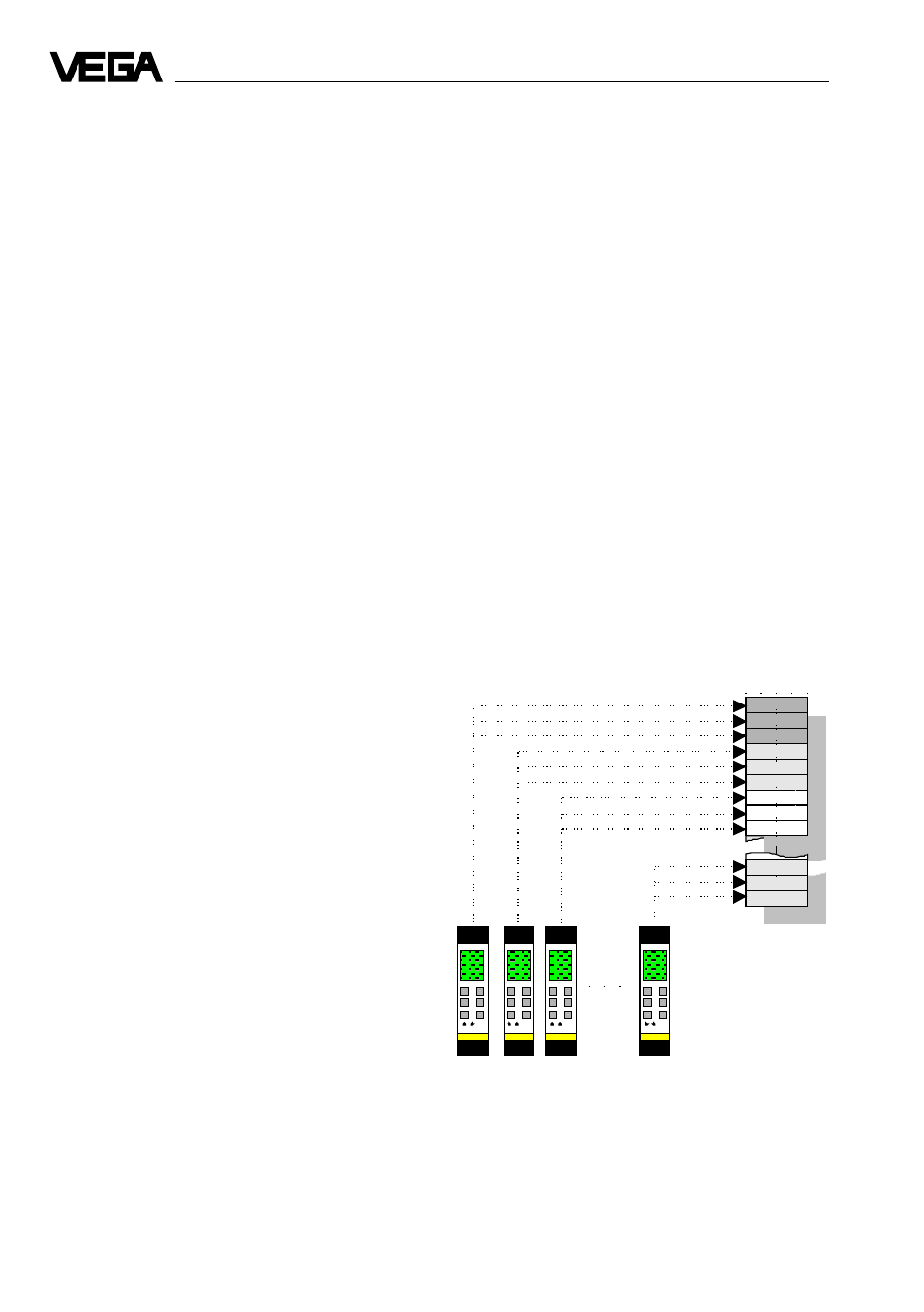
7 Data image in VEGACOM 557
all measured values
of VEGAMET #2
Grouping of measured values acc. to VEGAMET
addresses (here VEGAMET 513)
all measured values
of VEGAMET #15
all measured values
of VEGAMET #1
all measured values
of VEGAMET #3
VEGACOM 557 collects the measured values
of the VEGA signal conditioning instruments
VEGAMET series 500 and 600 (via DISBUS)
or VEGALOG 571 (via LOGBUS) and puts
them in the temporary memory for collection
via the Pr ofibus DP. The method of storing
the measur ed values (for the higher -priority
processing system) in the VEGACOM 557
temporary memory differs depending on the
selected configuration. It depends on
whether VEGACOM 557 is connected to the
DISBUS or the LOGBUS, and if DISBUS, also
on the connected instrument type. The alloca-
tion can, however, also be influenced via
appropriate inquiry protocols.
Note
On the VEGAMET 513, 514, 515 and series
600 signal conditioning instruments, as well
as on the VEGALOG 571 processing system,
the individual configuration of the PC/DCS
outputs with the adjustment software VVO is
possible (see chapter “4 Measurement loop
in VEGAMET/VEGALOG “).
On VEGAMET 513, 514, 515 and series 600
signal conditioning instruments as well as the
VEGALOG 571 processing system, it is
additionally possible to enquire the conditions
of the contact inputs/ and outputs via VEGA-
COM 557.
7.1 Image of measured value when
connecting to DISBUS
UP to 15 bus participants (VEGAMET) can
be connected to the DISBUS, whereby each
participant delivers max. 7 PC/DCS values.
The bus addresses 1 … 15 are configured
on the VEGAMET instruments, bus address 0
is not permitted. As already mentioned, the
storage of the measured values for the
VEGAMET signal conditioning instruments
can be influenced by the user . For this, the
operating mode of VEGACOM 557 and the
enquiry telegram (control command) of the
Profibus-Master are decisive.
Image of measured value DISBUS in
mode 50E2A
In this operating mode of VEGACOM 557, the
PC/DCS values are allocated as blocks relat-
ing to the VEGAMET bus address and the
PC/DCS output number .
A memory area of 16 PC/DCS values is re-
served for each VEGAMET . The allocation of
the individual PC/DCS values in blocks also
depends on the enquiry telegram (control
command) of the Pr ofibus-Master. Ther e are
two control commands to which the VEGA-
COM 557 reacts. The two control commands
0xCC or 0xCB are described in detail in the
following.
Control command 0xCC (DISBUS)
In case of an enquiry with this control com-
mand, the PC/DCS values will be grouped in
ascending sequence acc. to the VEGAMET
addresses.
In total, there are 32 blocks with 8 PC/DCS
values each.