2 measured value image when connecting to logbus, Image of measured value logbus in mode 50e2a – VEGA VEGACOM 557 Profibus DP User Manual
Page 38
38
VEGACOM 557 Profibus DP
7.2 Measured value image when
connecting to LOGBUS
VEGALOG 571 can manage up to 255 meas-
urement loops. For the transmission of the
measured values of a measurement loop,
VEGALOG provides up to 255 PC/DCS out-
puts. One or several PC/DCS outputs with
individual index can be allocated to each
measurement loop. The configuration of VE-
GALOG 571 is made with the VEGA adjust-
ment software VVO (see chapter 4)
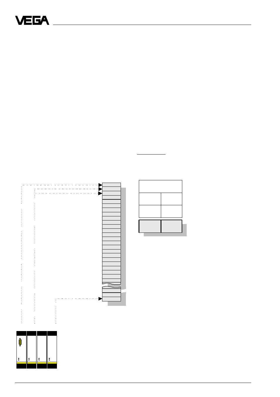
Image of measured value LOGBUS in
mode 50E2A
In this operating mode, the PC/DCS values
are reproduced in VEGACOM 557 in blocks
dependent on the PC/DCS output number .
Image of measured values when connecting to VE-
GALOG 571
DCS output 1
DCS output 2
DCS output 3
DCS output 255
Meas.
value
z
Meas.
value
x
Meas.
value
y
Data image in VEGACOM 557
2 Byte
output section
Byte 1
Byte 2
control
command Block no.
0xCC
0x01
...0x20
Enquiry of measured value from Profibus-Master
The allocation of the individual PC/DCS val-
ues in blocks is shown in a diagram. The
Profibus-Master has to send a control com-
mand to VEGACOM 557 to read the meas-
ured values out of VEGACOM 557.
Control command 0xCC (LOGBUS):
In case of an enquiry with this control com-
mand, the PC/DCS values are grouped in
ascending sequence acc. to the PC/DCS
output number. The measur ed value image
when connecting to LOGBUS is always gen-
erated with a sorting acc. to the PC/DCS
output number.
Enquiry of measured values:
DP-Master:
Control command:
0xCC
Block no.:
0x01...0x20