VEGA KLD2-PL(2)-1.PA PROFIBUS-PA Power Link Module User Manual
Profibus-pa power link module kld2-pl(2)-1.pa
PROFIBUS-PA Power Link Module
KLD2-PL(2)-1.PA
1
1
Subject to reasonable modifications due to technical advances.
Copyright Pepperl+Fuchs, Printed in Germany
Pepperl+Fuchs Group · Tel.: Germany (6 21) 7 76-22 22 · USA (3 30) 4 25 35 55 · Singapore 779 90 91 · Internet http://www.pepperl-fuchs.com
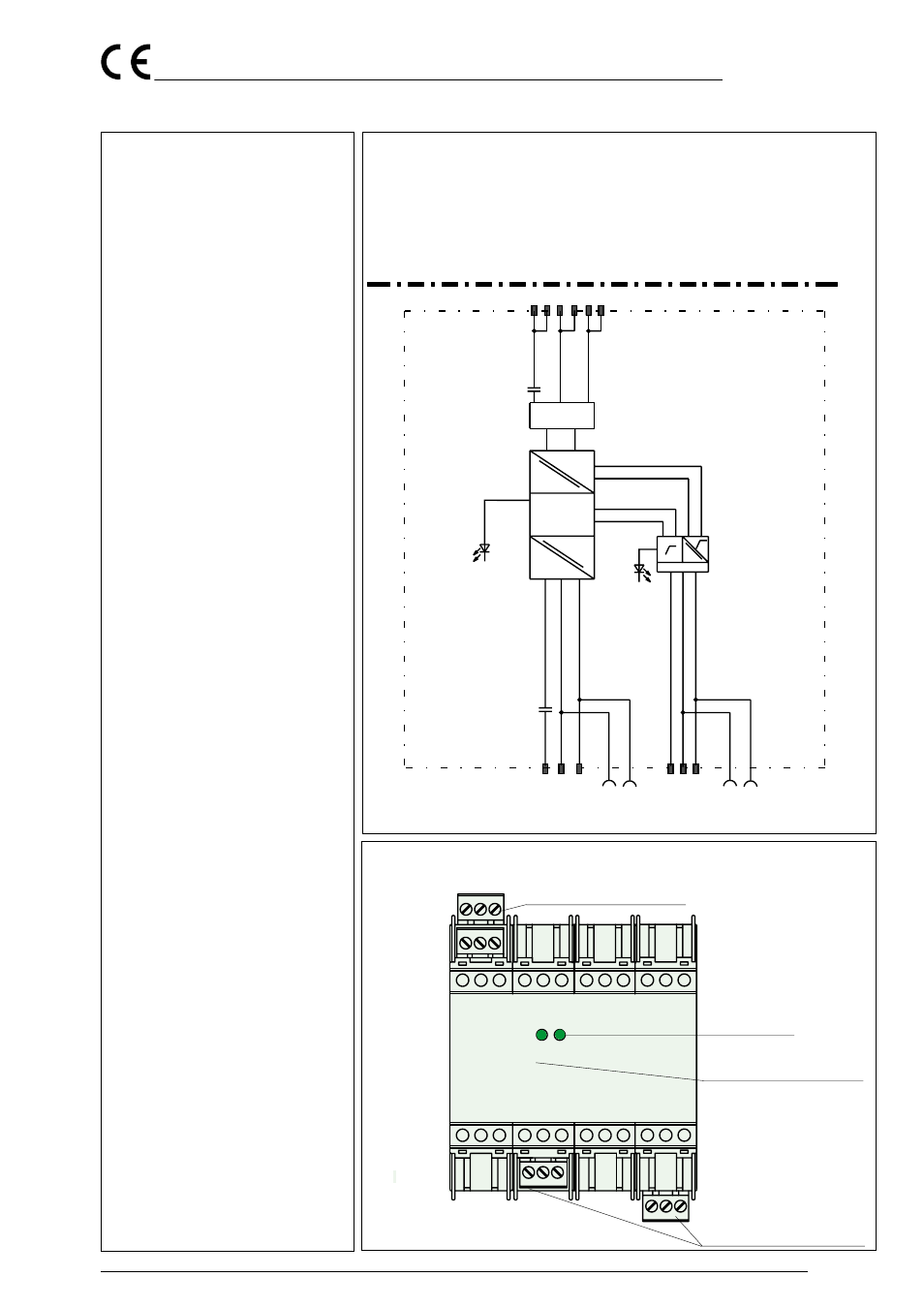
To Bridge Station KLD2-GT(2)-DP(R).xPA
Power Power Rail
Master channels 1 ... 4
Supply
IEC 61158-2
PROFIBUS-PA Segment
Bus
Termination
U
U
Shield/FE
green
red
Shield/PA
FE
+
-
- PROFIBUS-PA output per
EN 50 170/2 and IEC 61158-2;
31.25 kbit/s
- Installation in Zone 2
(KLD2-PL2-1.PA only)
- Up to 32 PROFIBUS PA I/Os can be
connected to the segment
- Supply voltage supplied by Power
Rail
- Nominal supply voltage 24 V DC
- Removable terminals and power rail
The Power Link Module forms a segment
coupler with the KLD2-GT(2)-DP(R).xPA
bridge station and can only operate with
this component. The KLD2-PL-1.PA is in-
stalled within a safe area and the KLD2-
PL2-1-PA can be mounted within Zone 2.
The Power Link Module therefore provides
an instrinsically safe interface per
IEC 61158-2. The Power Link supplies
PROFIBUS-PA I/Os powered by the bus.
The data transmission between Power Link
Module and bridge station KLD2-GT(2)-
DP(R).xPA Master 1 results by Power Rail.
Is the Power Link Module connected to
Master 2,3 or 4 of the bridge station a wire
Link for the data transmission has to be
made between Power Link Module termi-
nals and bridge station terminals.
The communication is seamless. The Po-
wer Link Module does not have to be
programmed.
The PROFIBUS-PA segment has a baud
rate of 31.25 kbit/s in accordance with
IEC 61158-2.
Note:
No external voltage have to be supplied to
the Profibus PA segment terminals. This
could lead to the destruction of the device.
Information on Installation of PROFIBUS
PA can be taken from PNO PROFIBUS
User Organisation Guideline.
P000357E
01/01 02
1
13
2
14
3
15
-
+
Physical
Conversion
+
-
30
28
29
46
47
48
1
2
3
4
5
6
7
8
9
10 11
12
13 14
15
16
17 18
19 20
21
22 23
24
Frontansicht
LED green: Power
LED red:
Hardware Error
Flashing: Communications
Error, no activity
on PROFIBUS-PA
Segment Line
25 26
27
28
29 30
31
32 33
34 35
36
37 38
39
40
41 42
43
44 45
46 47
48
removeable terminals green
removeable terminals green
COM/
ERR
PWR