Connections of the multiple plug (rear) – VEGA VEGACOM 557 Profibus DP User Manual
Page 16
16
VEGACOM 557 Profibus DP
Mounting and electrical connection
Multiple plug (rear of VEGACOM 557)
Supply voltage
GND (DGND)
DISBUS (not
used on VEGA-
LOG)
Profibus DP via RS 485
-
DATA (RxD/TxD-P)
/DATA (RxD/TxD-N)
+
-
+
+5V (VP)
d b z
10
8
6
4
2
12
14
16
18
20
22
24
26
28
30
32
Connection via modem
For remote parameter adjustment, it is possi-
ble to connect the PC interface via a modem.
In such a case, the modem cable that comes
with the respective modem should be used.
Modem operation is supported by VEGA-
COM 557 from software version 2.11. Further
information on the remote parameter adjust-
ment is stated in the operating instructions
„Remote parameter adjustment “.
Connections of the multiple plug (rear)
For connection of VEGACOM 557 to the ex-
isting Profibus DP system, a RS 485 interface
is available. The following diagram shows the
connections of the RS 485 interface, the
power supply of the instrument and the con-
nection to the VEGA system.
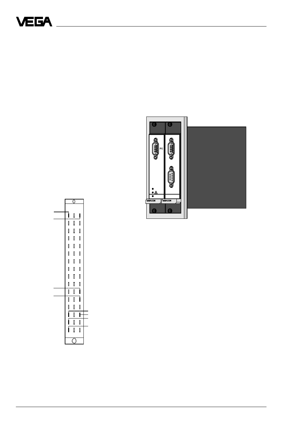
2.4 Mounting and installation in-
structions with VEGACOM 557AP
As an option, VEGACOM 557 can be ex-
tended with the adapter print VEGACOM
557AP. The adapter print VEGACOM 557AP
consists of a module card with 5 TE width
and two modules connected to a back-panel
print for carrier BGT 596 or BGT LOG 571.
With the adapter print card it is possible to
put the Profibus DP interfaces of VEGACOM
557 at the front of the carrier. On the fr ont of
the adapter print car d, the Pr ofibus DP inter -
face is available as a 9-pole SUB-D-plug and
as 9-pole SUB-D-socket. The r equired inter-
face type must be stated when ordering
VEGACOM 557AP.
The following interface types are available:
- RS 485 (Profibus DP)
Keep in mind that for Profibus, the interface
type RS 485 is necessary!
The pin assignments of the SUB-D-plug and
the SUB-D-socket are stated in the sched-
ules.
557
557AP
on
BA