7 indicating and adjustment elements, 7 indicating and adjustment ele- ments – VEGA VEGACOM 557 Profibus DP User Manual
Page 13
VEGACOM 557 Profibus DP
13
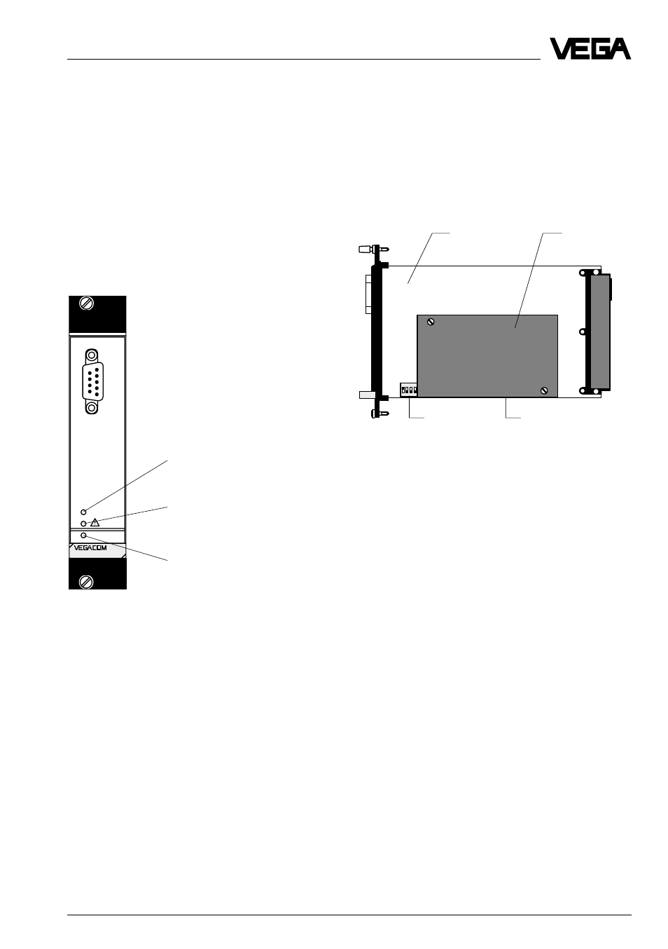
2 3 4
ON
1
Basic board
DIL switch
on additional board
Additional
board
DIL switch
on basic board
Side view of VEGACOM 557
Special function “Freeze Mode“
For diagnostic purposes on VEGA process-
ing systems VEGAMET and VEGALOG, the
process image can be “frozen“ in VEGACOM
557 with the adjustment software VVO. This
enables the possibility of carrying out mainte-
nance work on the VEGA system, without
disturbing the higher -priority pr ocessing
system.
For activating the Freeze Modes, a PC must
be connected directly to the PC interface of
VEGACOM 557 and the Freeze Mode must
be switched on under VVO in the menu „Con-
figuration - Measuring system “.
Attention:
Before activating this function, it must be
ensured that during this mode, no disastrous
consequences are to be expected for pro-
duction processes (during this mode, no
level values etc. are updated).
1.7 Indicating and adjustment ele-
ments
As diagnostic aid, VEGACOM 557 is
equipped with three LEDs. These are located
on the instrument front panel. In addition, the
basic board, as well as the additional board
of VEGACOM 557 are equipped with
switches (DIP switch or hook switch) for
configuration of the available interfaces.
Indicating elements/Diagnostics LEDs
Product description
on
557
BA
PC
Voltage supply
Fault signal
Modbus activity
Front of VEGACOM 557
Meaning of the LEDs:
VEGA ASCII active:
- green LED lights in case of valid data ex-
change
Fault signal:
- red LED flashing: DISBUS/LOGBUS-error
- irregularly flashing: no PC/DCS outputs
assigned
- permanent light: hardware error or special
function „Freeze Mode“
Voltage supply:
- green LED lights, operating voltage on.
Adjustment elements
The adjustment elements are located on the
basic board or on the additional board.
A 6-pole DIL switch block on the basic board
is used for adjustment of the fr ont PC inter-
face. The DIL switch and hook switch on the
additional board are used for adjustment of
the Profibus interface.