Basic properties of profibus fms and profibus dp, Protocol architecture – VEGA VEGACOM 557 Profibus DP User Manual
Page 75
VEGACOM 557 Profibus DP
75
Supplement C
Basic properties of Profibus FMS and
Profibus DP
PROFIBUS determines the technical and
functional properties of a series field bus
system, through which distributed, digital
field automation instruments in the lower (sen-
sor/actuator level) up to the medium (cell
level) power range can be connected.
PROFIBUS distinguishes between Master
and Slave instruments.
Master instruments
determine the data
traffic on the bus. A master can send mes-
sages without external request, provided the
master is authorised for bus access. In the
Profibus protocol, Masters are also called
active participants.
Slave instruments
are low-expenditure
peripherals. Typical Slave instruments ar e
sensors, actuators, transmitters. They do not
receive authorisation for bus access, i.e. they
are only allowed to acknowledge received
messages or transmit messages to a Master
on its request. Slaves are also called passive
participants. They require only a small portion
of the bus protocol, and as a result, a very
low-expenditure implementation of the bus
protocol is ensured.
Protocol architecture
PROFIBUS is based on a number of ap-
proved international and national standards.
The protocol architecture orients itself on OSI
(Open System Interconnection) multilayer
system, according to the international stand-
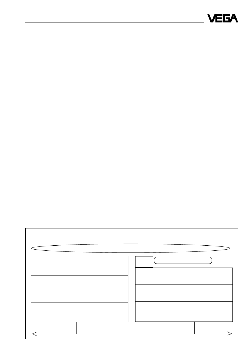
ard ISO 7498. The architecture of the Profi-
bus FMS and the Profibus DP protocol is
shown in figure 2.
PROFIBUS layer 1 (Physical Layer)
The application range of a Fieldbus system is
mainly determined by the selection of the
transmission medium and the physical bus
interface. Beside the demands on the trans-
mission r eliability, t he e xpenditures for pr o-
curement and installation of the bus cable are
of great consequence. That ’s why the Pr ofi-
bus standard makes provision for different
versions of transmission technology , while
keeping to a single, uniform bus protocol.
PROFIBUS layer 2 (Data Link Layer)
The second layer of the OSI multilayer sys-
tem realises the functions of the bus access
control and data backup, as well as the man-
aging of transmission protocols and tel-
egrams. Layer 2 is called Fieldbus Data Link
(FDL) with PROFIBUS.
Protocol architecture
Profibus DP
Profibus FMS
Application process
DIN (E)
User-Interface
PNO
Application Layer Interface (ALI)
19 245
Profile
part 3
Direct-Data-Link-Mapper (DDLM)
DIN
Application-Layer (7)
19 245
Fieldbus Message Specification (FMS)
Layer 3 to 7
part 2
Lower Layer Interface (LLI)
is not defined
Layer 3 to 6
is not defined
Subset of
Data-Link-Layer (2)
DIN
Data-Link-Layer (2)
DIN 19 245
Fieldbus Data Link (FDL)
19 245
Fieldbus Data Link (FDL)
part 1
Physical-Layer (1)
part 1
Physical-Layer (1)
Profibus transmission medium