VEGA VEGACOM 557 Profibus DP User Manual
Page 48
48
VEGACOM 557 Profibus DP
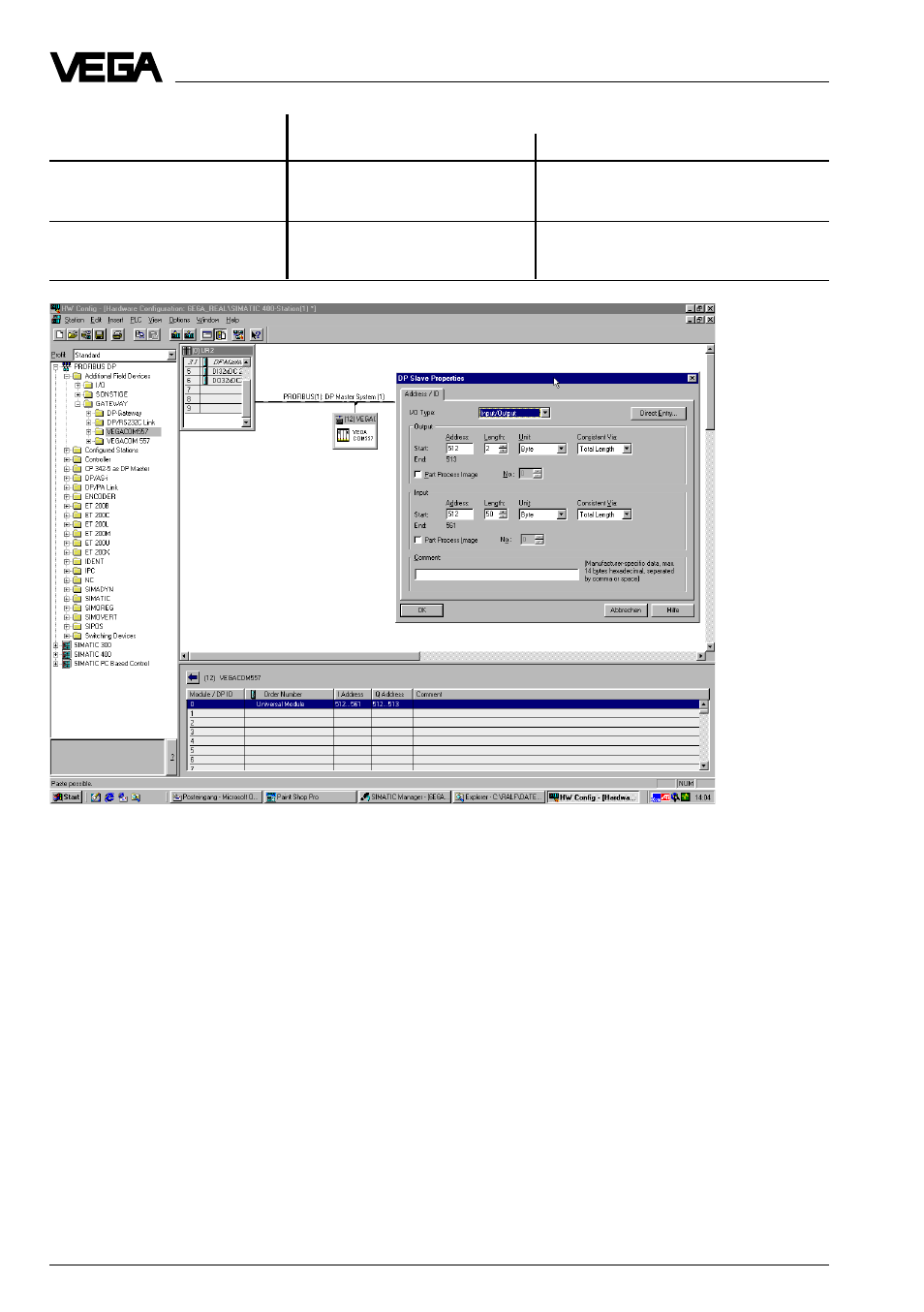
Providing of input and output addresses for VEGACOM 557
Setup
Length
Operating mode
input section (Byte)
Output section (Byte)
50 Byte IN, 2 Byte OUT
50
2
(50E2A)
6 Byte IN, 6 Byte OUT
6
6
(6E6A)
The planned output and input addresses are
important when using the example project on
the utility diskette. In the example project
(enquiry of FB 220) the two addresses must
be transferred as enquiry parameters (see
also „s7_doku.pdf“ on the utility diskette).
After the Profibus-Slave VEGACOM 557 has
been planned and the PLC loaded, the bus
error LED on the Profibus-Master must extin-
guish and the green „BA“-LED on VEGACOM
557 must light per manently. If this occurs, the
Profibus communication between PLC and
VEGACOM 557 is functioning.
Example projects on the utility diskette
An example program for the operating mode
50E2A and an example pr ogram for the oper -
ating mode 6E6A is available on the utility
diskette for reading measured values out of
VEGACOM 557. Further information on con-
figuration and function are included in the
PDF file „s7-doku.pdf“. To view the file, the
„Akrobat Reader “ is required. Please contact
VEGA Grieshaber KG if you need further
example programs or assistance.