VEGA VEGACOM 557 Profibus DP User Manual
Page 36
36
VEGACOM 557 Profibus DP
Image of the contact inputs/outputs on DISBUS in mode 6E6A
Beside the previously described individual PC/DCS measured values, also switching condi-
tions of the individual VEGA signal conditioning instruments VEGAMET 513, 514, 515 and
series 600 measured values can be transmitted via VEGACOM 557.
These are:
- status of the contact inputs (position of the key switch etc.)
- status of the contact outputs (relay or transistor outputs)
Control command 0xCE (DISBUS)
In contrast to the image of the measured values, the image of the switching conditions is „Bit
orientated“. One switch condition is represented in the VEGACOM 557 as one Bit, whereby all
available information of a VEGAMET is saved within one data word of 16 Bit
(= 2 Byte). Such a data word with 16 Bit, i.e. max. 15 data words at 16 bit each, is available for
each VEGAMET on the DISBUS (bus addresses 1...15). With the control command 0xCE the
switching status of two VEGAMET can be r ead out per enquir y, i.e. two data wor ds.
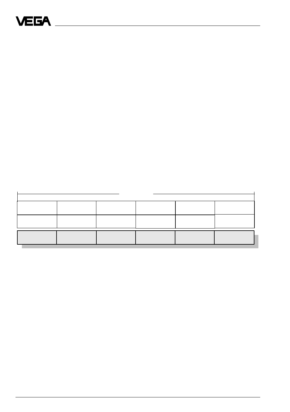
The enquiry telegram, written by the Profibus-Master into the 6 Byte outputs, is structured as
follows.
Byte1
Byte2
Byte3
Byte4
Byte5
Byte6
control
command
reserved
VEGAMET
address
reserved
reserved
reserved
0xCE
1...15
0xFF
0xFF
0xFF
0xFF
6 Byte
Format of the enquiry acc. to contact inputs/outputs (DISBUS)
Data image in VEGACOM 557
VEGACOM 557 writes the answering telegram (show on the following page) into the 6 Byte
inputs of the Pr ofibus-Master. The DISBUS dif ferentiates in the data wor d between input con-
tacts (EK) and relay contacts (RK). The input contacts are bit coded in the High-Byte, the relay
contacts in the Low-Byte of the data word.