2 mounting in carrier and housing, 3 wiring plan vegacom 557, Rxd txd gnd – VEGA VEGACOM 557 Profibus DP User Manual
Page 15: Pc interface in front panel (sub-d- plug), Pin description i/o
VEGACOM 557 Profibus DP
15
2.2 Mounting in carrier and housing
BGT 596 or BGT LOG 571
For mounting, a slot module must be pro-
vided at the location. A slot module consists
of:
- a multipoint connector acc. to DIN 41 612,
series F, 33-pole (d, b, z)
- two screws
- three coded pins
- two guide rails.
The multipoint connector is available in the
following versions:
- Wire-Wrap, standard connection
1.0 mm x 1.0 mm
- plug connection
2.8 mm x 0.8 mm
- Termi-Point standar d connection
1.6 mm x 0.8 mm
- soldering connection
- screw terminals 0.5 mm
2
.
For mounting the module, please note the
operating instructions of the carrier .
Housing type 505, type 506
This housing is already equipped with a
multipoint connector. Before mounting, please
check if the housing is equipped with a
power supply unit or not.
The connection is made via screw terminals
with max. 1.5 mm
2
. Further details are stated
in the operating instructions “Housing type
505, type 506 “.
Wiring proposal for interlink cable
1
2
6
4
3
7
8
9
5
RxD
TxD
GND
1
2
6
4
3
7
8
9
5
1
2
6
4
3
7
8
9
5
Mounting and electrical connection
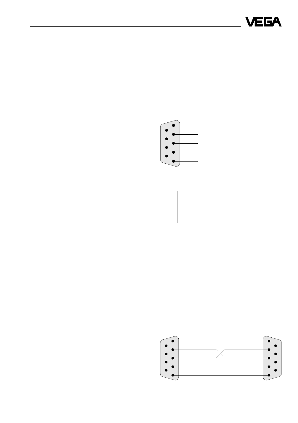
2.3 Wiring plan VEGACOM 557
PC interface in front panel (SUB-D-
plug)
The PC interface of VEGACOM 557 is used
exclusively for connection of computer sys-
tems with VEGA adjustment software via a
COM-Port. The PC interface is based on the
RS 232C standard and is assigned as fol-
lows.
Pin
Description
I/O
2
RxD
receive data
I
3
TxD
transmit data
O
5
GND
ground
–
Note:
With a direct connection to the computer
system, VEGACOM 557 works without hard-
ware handshake.
Direct connection
For direct connection of a PC to the PC inter -
face of VEGACOM 557, the interlink (or a
standard) cable available from VEGA with 9-
pole plugs on both ends should be used.
The pin assignments of the interlink cable are
shown in the diagram.
Pin assignments of the PC interface of VEGACOM 557