Data outputs product diagram, Display screen diagram, Lcd screen: buttons – Veris Industries E51C3 Install User Manual
Page 5
ZL0067-0C
Page 5 of 34
©2013 Veris Industries USA 800.354.8556 or +1.503.598.4564 / [email protected] 06131
Alta Labs, Enercept, Enspector, Hawkeye, Trustat, Aerospond, Veris, and the Veris ‘V’ logo are trademarks or registered trademarks of Veris Industries, L.L.C. in the USA and/or other countries.
Other companies’ trademarks are hereby acknowledged to belong to their respective owners.
Installation Guide
Power Monitoring
E51C2, E51C3
TM
Signed Power: Real, Reactive, and Apparent 3-phase total and per phase
Real and Apparent Energy Accumulators: Import, Export, and Net; 3-phase total and per phase
Reactive Energy Accumulators by Quadrant: 3-phase totals and per phase
Configurable for CT & PT ratios, system type, and passwords
Diagnostic alerts
Current: 3-phase average and per phase
Volts: 3-phase average and per phase Line-Line and Line-Neutral
Power Factor: 3-phase average and per phase
Frequency
Power Demand: Most Recent and Peak (Import and Export)
Demand Configuration: Fixed, Rolling Block, and External Sync (Modbus only)
Data Logging (E51C3 only)
Real Time Clock: user configurable
10 user configurable log buffers: each buffer holds 5760 16-bit entries
(User configures which 10 data points are stored in these buffers)
User configurable logging interval
(When configured for a 15 minute interval, each buffer holds 60 days of data)
Continuous and Single Shot logging modes: user selectable
Auto write pause: read logs without disabling the meter’s data logging mode
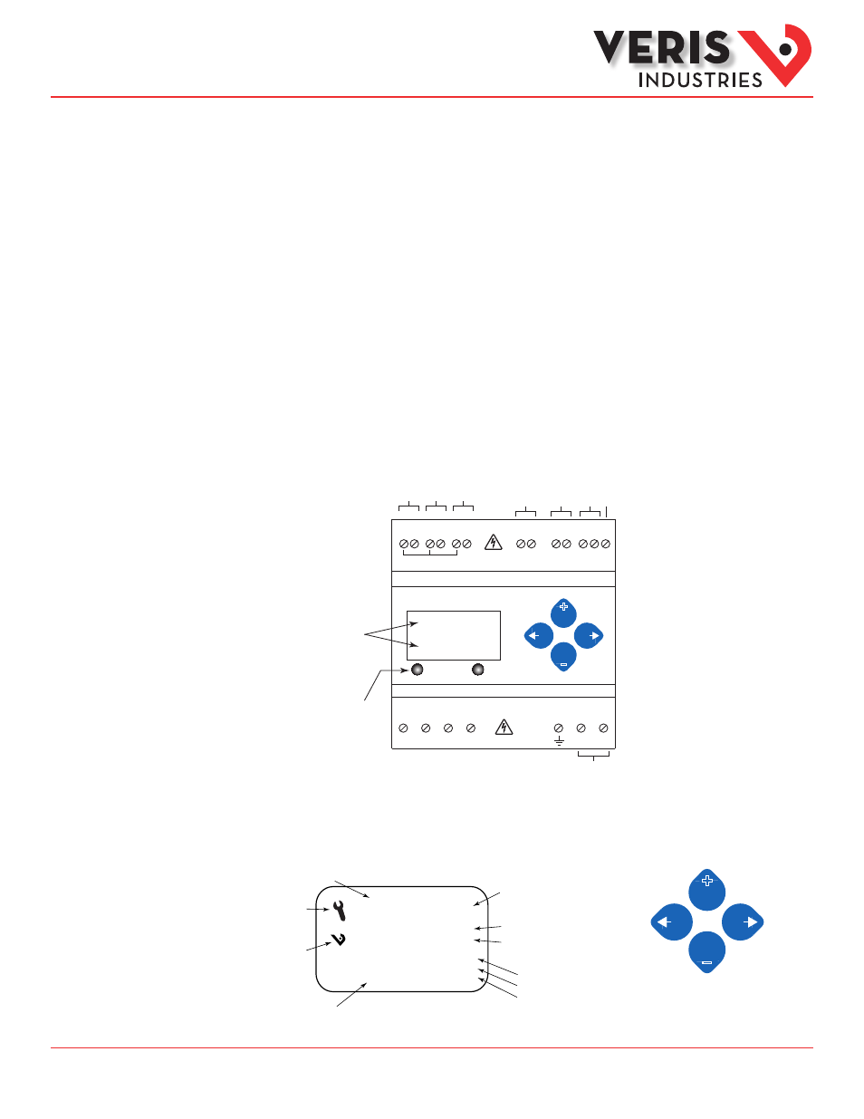
Data Outputs
Product Diagram
Alarm
Energy
kWh
1234.5
Two 5-character rows
of display text.
Top row alphanumeric;
Bottom row numeric only
The red Alarm LED lights when
any of the 3 phase voltages
drop below the selected thresh-
old. The green Energy LED lights
momentarily each time the
Energy output pulse is active.
CONTROL POWER
0.1A 50/60 Hz
A
B
C
N
1
2
A
B
C
Alarm
Energy
NC
NO
+ - S
OUTPUT
Common - 1 or 1/3 VAC Input
-
+
-
+
-
+
IA
IB
IC
Phase L
oss
Alarm
Pulse
Modbus
Shield
VA
VB
VC
Neutr
al
Ear
th
Con
trol
Po
we
r
UL: 90V
L-N
- 600V
L-L
CE: 90V
L-N
- 300V
L-N
VOLTAGE INPUTS
CAT III 50/60 Hz
+
–
LCD Screen:
Buttons:
+
–
(Up)
Select
(Right)
Next
(Down)
Select
(Left)
Back
Tx
Rx
ERR
♥
Screen Name or Units
Diagnostic Alert
Logo
Numeric Data
Alive Indicator
Transmit Data
Receive Data
Receive Data Error
Export
Import
Display Screen
Diagram