Trouble shooting – M&C TechGroup CSS-V2 Operator's manual User Manual
Page 26
26
Gas sampling and gas conditioning technology
4-1.2-ME
17
TROUBLE SHOOTING
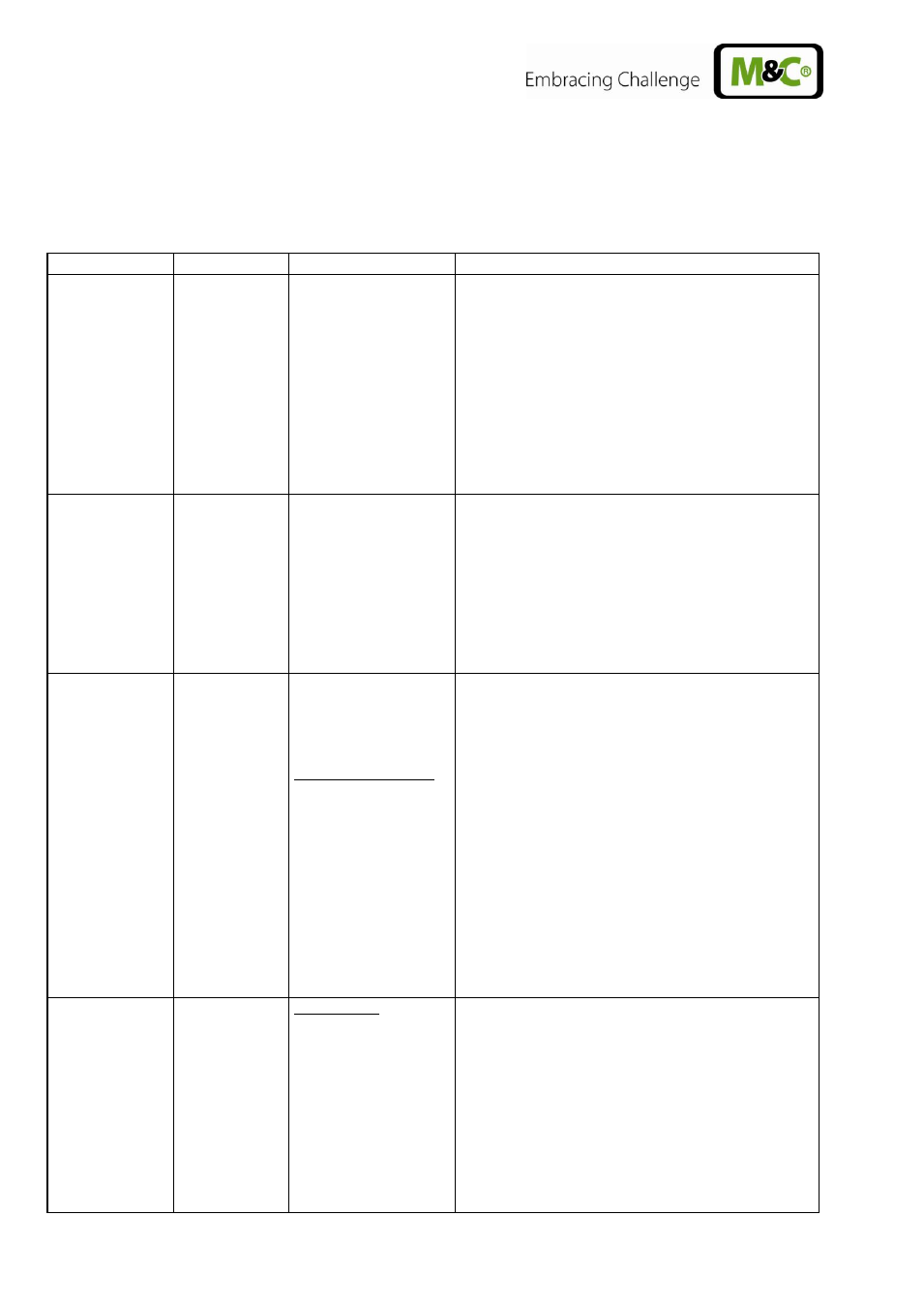
The following table shows possible sources of errors and how to remove them (not applicable for the
starting-up phase).
Display
Fault
Possible cause
Examination/Correction
None
No supply voltage;
Check the supply voltage according to the type
plate;
ok?
Control whether the mains plug is put in correctly;
ok?
Examine the fine fuses F1, F2 in the cold appliance
socket;
ok?
LED K1 is
beaming
permanently
and temp. > 8°C
Cooler alarm „Excess
temperature“; cooler
switches off the
sample gas pump
automatically if
existing;
Ventilator does not
function
Ambient temperature too high;
ok?
Free convection inside the gas conditioning unit
upset internal temperature too high;
ok?
Sample flow or dew point too high? Reduce flow.
ok?
Return the instrument for repair to M&C.
Temp.
>2°C and
< 7,5°C
Cooler runs,
sample flow is
interrupted;
Pump
defective
Diaphragm pump
does not work;
Liquid alarm sensor:
Sensor turns sample
gas pump
automatically off;
LED Liquid alarm is beaming red.
Liquid in the filter (Dry filter and liquid alarm sensor
and check peristaltic pump, see below.)
ok?
Check the hoses for condensate draining;
ok?
Check pump hose (see 15.3.1);
ok?
Check pump SR25.2 (see 15.3);
ok?
Return instrument for repair to M&C.
Pump works,
but sample
gas flow is
interrupted;
Flow meter :
Needle valve is shut.
Sample probe or
sample hose clogged
or line squeezed;
Set the desired flow rate on the needle valve.
Loosen the sample hose from the sample gas inlet
of the gas conditioning unit (see 12.1);
Gas flow?
Clean the clogged line or replace it;