Figure 10, Disassembly of pump head and driver, Figure 11 – M&C TechGroup CSS-V2 Operator's manual User Manual
Page 23: Check of axes and rolls
4-1.2-ME
Gas sampling and gas conditioning technology
23
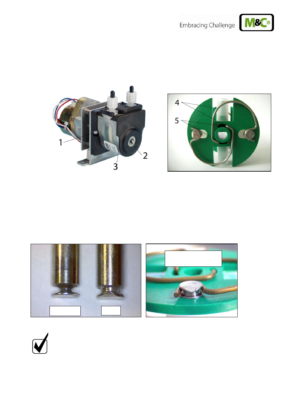
15.3.2 CHANGE OF CONTACT PULLEYS AND SPRINGS
Switch off the mains;
Unscrew nuts of the pump head (wrench size 5,5) and remove snap ring from motor
shaft;
Figure 10
Disassembly of pump head and driver
Draw the pump head out of the motor shaft
Take driver out of the pump head
The removal of the springs (4 pcs.) away from the driver is easily possible without the aid of
any tools. For this take spring out of the groove near to the shaft bore.
Dismount roller axes and change contact pulleys. Take care that axes are not worn out by the
springs and have damaged the dent at the axes front end. In case of abrasion the axes have to
be changed (see Figure 11).
Figure 11
Check of axes and rolls
N O T E !
The springs may occur in different coulerings. This does not constitute a
quality defect. But make sure that the right spring strength is used. This
can be identified by the spring wire diameter.
The „standard version for
Novoprene pump hoses
“ (part no. 90P1010) has a diameter of 1,1mm and
the strengthened version for FPM-, Acidflex- or Masterflex-hoses
“ (part
no. 90P1015) has a diameter of 1,2mm.
The dent prevents
rotation of the axis
new
worn out