Description, Figure 3, Design css-v2 – M&C TechGroup CSS-V2 Operator's manual User Manual
Page 12
12
Gas sampling and gas conditioning technology
4-1.2-ME
9
DESCRIPTION
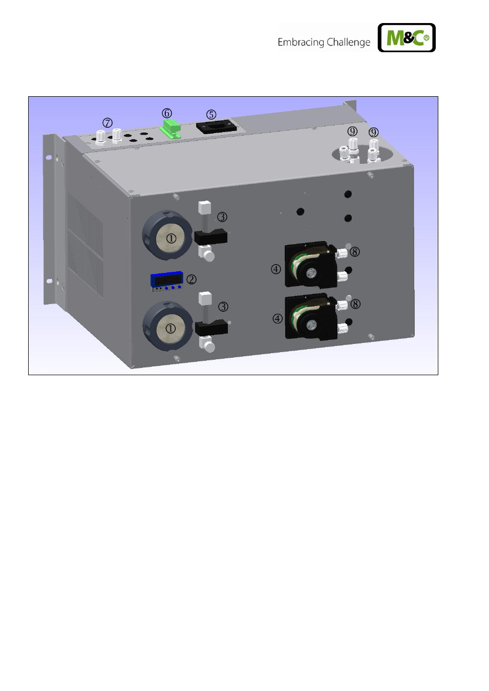
Figure 3
Design CSS-V2..
Fine filter FPF-2-0,3GF
Electronic controller
Flow meter FM40 with flow alarm sensor FA-20mo
Peristaltic pump SR25.2 with condensate outlet
Cold appliance socket
Connection for summery alarm
Sample gas outlets
Condensate outlet directly at the peristaltic pump
Sample gas inlet directly at the heat exchanger
All components of the gas conditioning unit are mounted in a compact sheet steel case. Filter and
peristaltic pump are placed into the front panel and thus assure a very easy maintenance.
The minimum flow is determined by the gas sampling pump (see also chapter 13). Premature damage
can be caused to the pump membrane if less than the minimal total amount of flow is extracted as a
result of excess pressure.
The gas cooler is equipped with a heat exchanger of Duran glass, stainless steel SS316Ti or PVDF.
The fine filter FPF-2-0,3GF (0,3µm filter fineness) installed in front of the sample gas pump
N3/5/9 KPE ensures the necessary removal of solid particles.
The instrument contains a temperature alarm contact that is activated in case the temperature differs
more than +/-3 °C from the set value (+ 5°C) adjusted at the factory and switches off the sample gas
pump if existing. The temperature alarm contact of the cooler (
+8°C or
+2°C) controls automatically
the switching on and off of the sample gas pump.
The condensate occurred is removed continuously via the peristaltic pump type SR25.2.