Omron HOME SECURITY SYSTEM - MOTION SENSOR FQM1-MMA21 User Manual
Page 99
76
Wiring Servo Relay Units
Section 3-4
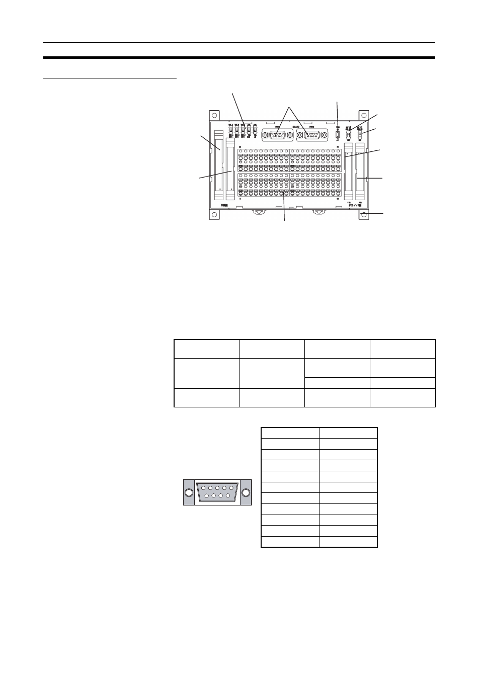
Nomenclature and Functions
1,2,3...
1.
Motion Control Module 40-pin Connector
Connects to the 40-pin connector on the Motion Control Module.
2.
Motion Control Module 34-pin Connector
Connects to the 26-pin connector on the Motion Control Module. The Mo-
tion Control Module general-purpose I/O is allocated to the clamp terminal
block.
3.
Servo Driver Connectors
Connects to two Servo Drivers.
4.
RS-422 Connector
5.
Screw-less, Clamp Terminal Block (80 Terminals)
The clamp terminal block is used for the Motion Control Module general-
purpose I/O and the Servo Driver control signals. It is also used for external
device connections, such as analog inputs and latch signal inputs.
1. Motion
Control
Module 40-pin
connector
2. Motion
Control
Module 34-pin
connector
6. Signal switches
4. RS-422 connectors
7. Terminating resistance switch
8. Servo Driver # 2
phase B switch
8. Servo Driver # 1
phase B switch
3. Servo Driver #2
connector
3. Servo Driver #1
connector
Mounting hole
(Can be mounted
to DIN Track.)
5. Screw-less Clamp Terminal
Block (40 terminals each on
upper and lower tiers)
Motion Control
Module
Corresponding
connecting cable
Servo Driver
cable
Servo Driver
FQM1-MMP21
XW2Z-
@@@J-A28
XW2Z-
@@@J-A30
XW2Z-
@@@J-B9
W-series Servo
Driver
XW2Z-
@@@J-B10 SMARTSTEP
FQM1-MMA21
XW2Z-
@@@J-A28
XW2Z-
@@@J-A31
XW2Z-
@@@J-B13 W-series Servo
Driver
Pin No.
Signal
1
TXD
−
2
TXD+
3
---
4
---
5
---
6
RXD
−
7
---
8
RXD+
9
---
Case
FG