6-15 pulse output starting conditions, Pulse output starting conditions, One-shot pulse output function example – Omron HOME SECURITY SYSTEM - MOTION SENSOR FQM1-MMA21 User Manual
Page 217: Pulse counter time measurement (timer) example
194
Pulse Outputs
Section 7-6
get Frequency Not Reached Flag (A624.02 or A625.02) will turn ON at the
peak of the triangular pattern and turn OFF when deceleration is completed.
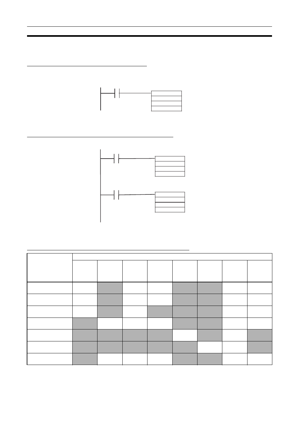
One-shot Pulse Output Function Example
In this example, STIM(980) is used to generate a 1.5-ms one-shot pulse out-
put from pulse output 1.
Pulse Counter Time Measurement (Timer) Example
In this example, a pulse counter timer is allocated to pulse output 1.
7-6-15 Pulse Output Starting Conditions
Pulse Output Operation Modes Supported by Instruction
Note
(1) Even if the PV is changed, it will start from 0 at startup.
(2) Supports continuous mode only.
@STIM
#1
#000F
#0
0002.00
When CIO 0002.00 goes ON, STIM generates a
1.5-ms one-shot pulse output from port 1.
@STIM
#B
#0
#0
0002.00
@STIM
#B
#1
#0
0003.00
When CIO 0002.00 goes ON, STIM starts
pulse counter timer 1 (allocated to port 1).
When CIO 0003.00 goes ON, STIM stops
pulse counter timer 1.
The measurement results are stored in
Auxiliary Area words A620 and A621.
Pulse output
operation mode
Starting instruction
SPED(885) PULS(886)
(with
output)
ACC(888) PLS2(887) STIM(980)
(One-shot)
STIM(980)
(Timer)
INI(880)
(Change
PV)
INI(880)
(Stop
pulse
output)
Relative pulse output OK
No
OK
OK
No
No
OK
(note 1)
OK
Absolute pulse output
(linear)
OK
No
OK
OK
No
No
OK
OK
Absolute pulse output
(circular)
OK
No
OK
No
No
No
OK
OK
Electronic Cam Con-
trol (linear)
No
OK
OK
(note 2)
OK
(note 3)
No
No
OK
OK
One-shot pulse mode No
No
No
No
OK
No
OK
(note 1)
No
Pulse counter timer
No
No
No
No
No
OK
OK
(note 1)
No
Electronic Cam Con-
trol (circular)
No
OK
OK
(note 2)
OK
(note 3)
No
No
OK
OK