Omron HOME SECURITY SYSTEM - MOTION SENSOR FQM1-MMA21 User Manual
Page 356
333
System Setup, Auxiliary Area Allocations, and Built-in I/O Allocations
Appendix C
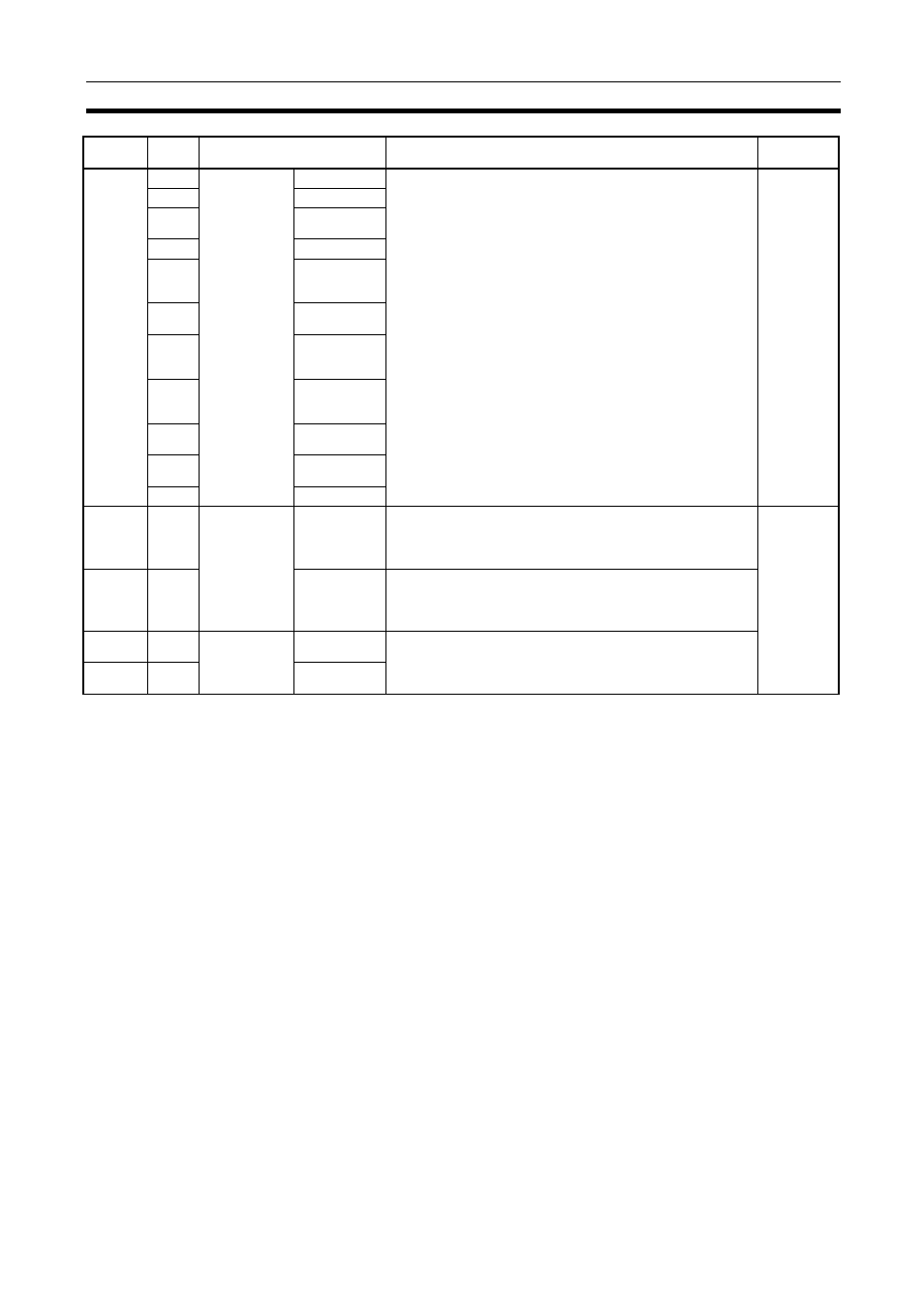
A611
00
High-speed
counter 2 com-
mand bits
Start Bit
Same as command bits for high-speed counter 1.
User
01
Reset Bit
02
Measurement
Start Bit
03
Reserved
04
Range Com-
parison Results
Clear Bit
05
Absolute Off-
set Preset Bit
06
Absolute
Present Value
Preset Bit
07
Absolute Num-
ber of Rota-
tions Read Bit
08
Latch Input 1
Enable Bit
09
Latch Input 2
Enable Bit
10 to 15
Reserved
A612
00 to 15 High-speed
counter 1 moni-
tor data
Range Com-
parison Execu-
tion Results
Flags
Contains the CTBL(882) execution results for range comparison.
Bits 00 to 15 correspond to ranges 1 to 16.
OFF: No match
ON: Match
Module
A613
00 to 15
Output Bit Pat-
tern
Contains the output bit pattern when a match is found for
CTBL(882) execution results for range comparison
Note If more than one match is found, an OR of the output bit pat-
terns with matches will be stored here.
A614
00 to 15 High-speed
counter 2 moni-
tor data
Range Com-
parison Results
Same as for high-speed counter 1 monitor data.
A615
00 to 15
Output Bit Pat-
tern
Address
Bits
Name
Function
Controlled
by