Omron HOME SECURITY SYSTEM - MOTION SENSOR FQM1-MMA21 User Manual
Page 368
345
System Setup, Auxiliary Area Allocations, and Built-in I/O Allocations
Appendix C
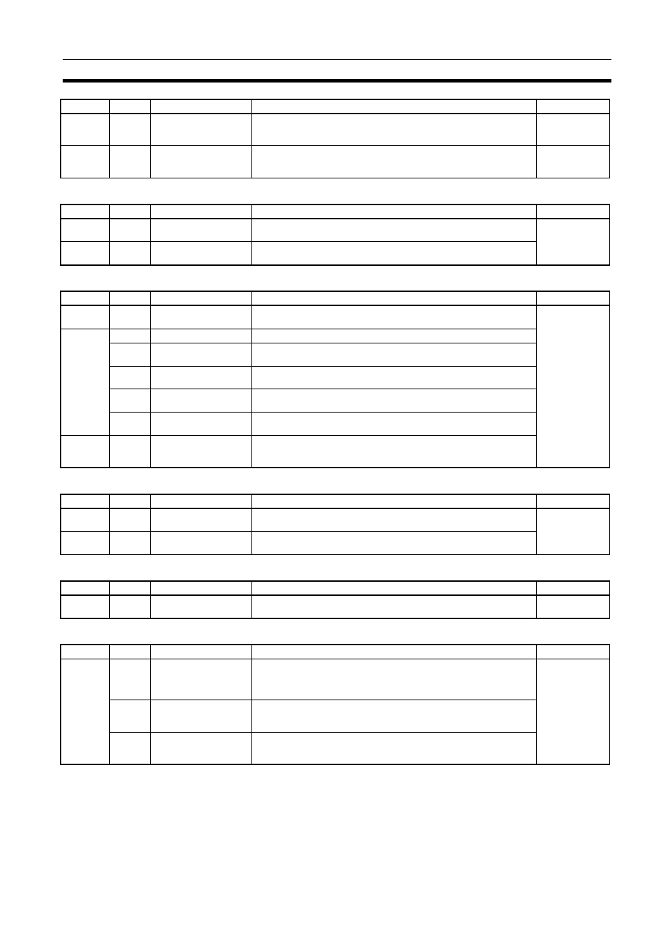
FAL/FALS Errors
Memory Errors
System Setup
I/O Errors
Module Errors
A500
14
Error Log Pointer Reset
and Memory Not Held
Flag OFF Bit
The error log pointer in A408 is reset to 0000 hex and Memory Not
Held Flag (A404.14) is turned OFF when this bit is turned ON.
User
A400
00 to 15 Error code
When a non-fatal error (user-defined FAL(006) or system error) or a
fatal error (user-defined FALS(007) or system error) occurs, the hexa-
decimal error code is written to this word.
Module
Address
Bits
Name
Function
Controlled by
A401
06
FALS Error Flag
(fatal error)
Turns ON when a non-fatal error is generated by the FALS(006)
instruction. The FQM1 will stop operating.
Module
A402
15
FAL Error Flag
(non-fatal error)
Turns ON when a non-fatal error is generated by executing FAL(006).
The FQM1 will continue operating.
Address
Bits
Name
Function
Controlled by
A401
15
Memory Error Flag (fatal
error)
Turns ON when there is an error in the memory. FQM1 operation will
stop and the ERR indicators on the front of the Modules will light.
Module
A403
00
UM Error Flag
Turns ON when there is an error in the user memory.
04
System Setup Error
Flag
Turns ON when there is an error in the System Setup in the Coordina-
tor Module or Motion Control Module.
10
Flash Memory Error
Flag
Turns ON when the flash memory is physically destroyed.
13
Analog Offset/Gain
Error Flag
Turns ON when there is an error in the analog I/O offset/gain adjust-
ment value in flash memory.
14
Flash Memory DM
Checksum Error Flag
Turns ON when there is an error in the DM Area data backed up in
flash memory in the Coordinator Module.
A404
14
Memory Not Held Flag
Turns ON when corruption is found in the check performed after turn-
ing ON power in the areas backed up during power interruptions (DM
Area (Coordinator Module only) and Error Log Area).
Address
Bits
Name
Function
Controlled by
A402
10
System Setup Error
Flag
Turns ON when there is a setting error in the System Setup.
Module
A409
00 to 15 System Setup Error
Location
When there is a setting error in the System Setup, the location of that
error is written to A409 in 4-digit hexadecimal.
Address
Bits
Name
Function
Controlled by
A401
10
I/O Setting Error Flag
Turns ON when more than four Motion Control Modules are connected
to the Coordinator Module.
Module
Address
Bits
Name
Function
Controlled by
A402
05
Motion Control Module
Monitoring Error Flag
(Coordinator Module
only)
Turns ON in the Coordinator Module when a system error, such as a
WDT error, occurs in any of the Motion Control Modules.
Module
13
Coordinator Module
WDT Error Flag (Motion
Control Modules only)
Turns ON in the Motion Control Modules when a WDT error occurs in
the Coordinator Module.
14
Coordinator Module
Fatal Error Flag (Motion
Control Modules only)
Turns ON in the Motion Control Modules when a fatal error occurs in
the Coordinator Module.
Address
Bits
Name
Function
Controlled by