15—r-bus 1 and 2 digital 8ch i/o jacks, 16—optical and coaxial digital audio connectors – Roland VS-2480 User Manual
Page 49
2—Getting Around
Roland VS-2480 Owner’s Manual
www.rolandus.com
49
15—R-BUS 1 and 2 DIGITAL 8ch I/O Jacks
Using Roland’s R-BUS technology, you can bring digital audio into and out of the
VS-2480 by connecting it to any R-BUS-compliant external digital device. This includes
the following Roland products (purchased separately):
•
ADA-7000 8-Channel A/D-D/A Converter that provides additional analog inputs
•
AE-7000 AES/EBU Interface that provides AES-EBU connectivity
•
The RPC-1 R-BUS Interface Card for exchanging digital audio with a computer
•
The VM-7000 V-Mixing system
•
The VM-3100Pro V-Mixing Station
•
XV-5080 128-Voice Synthesizer/Sample Playback Module
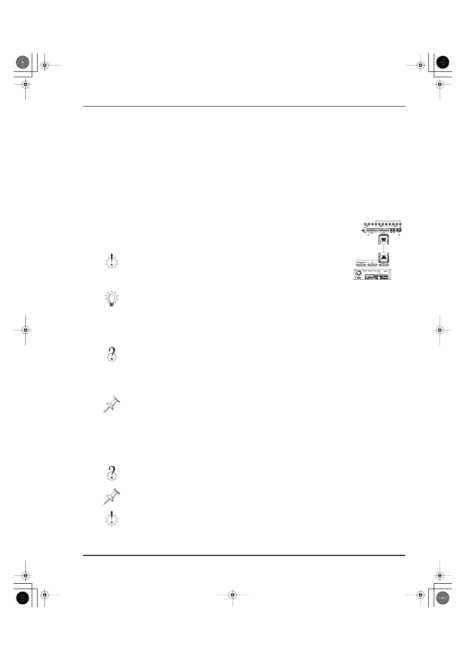
To connect the VS-2480 to another R-BUS device, connect one
end of an R-BUS cable to the VS-2480’s R-BUS 1 jack or R-BUS
2 jack, and the other to an R-BUS jack on the external device.
Each R-BUS jack can both receive and send eight separate digital audio signals, so only
one connection is needed between two R-BUS devices. R-BUS connections can also
carry MIDI, MMC and MTC data in both directions.
See Page 377 to learn how to configure a connected R-BUS device. Page 131 describes
how to activate R-BUS 2, coaxial and optical inputs. See Page 288 to learn how to route
the desired signals to your R-BUS outputs.
16—OPTICAL and COAXIAL Digital Audio Connectors
The VS-2480 can both receive and transmit S/P DIF-format digital audio via its optical
and coaxial digital IN and OUT connectors. Each connector carries a stereo digital
audio signal. See Page 132 to learn how to successfully handle incoming digital audio.
We’ll explain how to route signals to either OUT connector starting on Page 288.
Be sure to use the shortest Roland-approved R-BUS cables
possible. Note that other cables—such as SCSI, RS-232C
or parallel cables—may have connectors that look like
R-BUS connectors, but they’re not the same, and these
cables can’t be used successfully with R-BUS jacks.
If you plan to use only one of the VS-2480’s R-BUS jacks, use the R-BUS 1 jack, whose
eight channels of digital audio are always available. The full set of eight channels
associated with the R-BUS 2 jack is available only when you’re not using the coaxial
and optical digital inputs, as described on Page 131.
MMC
R-BUS was formerly called “RMDB II “or “RMDB2” in earlier Roland products.
S/P DIF
You can configure the VS-2480 to record digital audio received from an external digital
device connected to these jacks—see Page 134.
The coaxial IN and OUT jacks carry
only
S/P DIF digital audio signals. The IN jack
won’t accept standard analog audio signals, and the OUT jack doesn’t produce them.
WORD CLOCK IN
R
L
R
L
R
L
FOOT
SWITCH
MONITOR
AUX A
AUX B
3
4
R
L
MASTER
1
2
5
6
7
8
PHONES 1
PHONES 2
ANALOG MULTI OUTPUT
OUT
IN
OUT
IN
DIGITAL
OPTICAL
2
COAXIAL
DIGITAL 8ch I / O
DIGITAL 8ch I / O
1
+4dBu BALANCED / -2dBu UNBALANCED
VS-2480
VM-7000 Series + VM-24E
VS2480OMUS.book 49 ページ 2006年2月7日 火曜日 午後4時16分