2—getting around, The top panel of the vs-2480, Analog input jacks – Roland VS-2480 User Manual
Page 31: 1—xlr inputs 1-8, 2—trs inputs 1-16, 2—getting around 31
Roland VS-2480 Owner’s Manual
www.rolandus.com
31
2—Getting Around
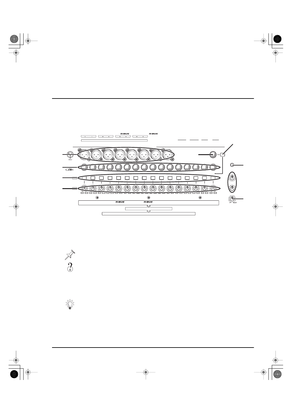
The Top Panel of the VS-2480
Analog Input Jacks
The analog input jacks allow you to bring analog audio into the VS-2480’s 24-bit analog-
to-digital (A/D) converters using balanced XLR connectors and balanced or
unbalanced 1/4” connectors. The VS-2480 also provides -20 dB pads and level
sensitivity adjustment knobs for each input jack. We’ll explain how to correctly set an
analog input’s level in “Setting Analog Input Levels” on Page 130.
1—XLR Inputs 1-8
Each of the eight XLR input jacks accepts an input signal from a balanced XLR
connector.
2—TRS Inputs 1-16
Connect a 1/4” phone-type TRS balanced or unbalanced audio connector to any of the
sixteen TRS input jacks.
Don’t use the same-numbered XLR and TRS input jack—each pad and SENS knob
controls both jacks, so you won’t have independent control of the two jacks’ signals.
Analog, 24-bit, balanced, XLR, unbalanced, TRS, dB, pad
The VS-2480 can provide phantom power for a condenser-type mic connected to an
XLR jack. See “To Turn an XLR Input Jack’s Phantom Power On or Off” on Page 130.
VGA OUT
WORD CLOCK IN
SCSI
KEYBOARD
SMPTE
IN
MOUSE
PS / 2
PUSH
20 dB
0
10
PHONES 2
0
10
PHONES 1
MONITOR
(TIP)
(RING)
(SLEEVE)
HOT
COLD
GND
PAD
dBu
SENS
ANALOG INPUT
1
2
3
4
5
6
7
8
9
10
11
12
13
14
15
16
1
2
3
4
5
6
7
8
9
10
11
12
13
14
15
16
GUITAR
Hi-Z
CONTRAST
ON
-6
-64
-6
-64
-6
-64
-6
-64
-6
-64
-6
-64
-6
-64
-6
-64
-6
-64
-6
-64
-6
-64
-6
-64
-6
-64
-6
-64
-6
-64
-6
-64
MASTER
L
R
AUX A
L
R
AUX B
L
R
MONITOR
L
R
MIDI
2
1
4
3
6
5
PHONES 1 PHONES 2
SWITCH
FOOT
8
7
1
2
IN
OUT / THRU
1
2
3
4
5
6
7
8
ANALOG MULTI OUTPUT
PATCH BAY
INPUT MIXER
ANALOG INPUT
1
1-8
2
1-8
COAXIAL
OPTICAL
CORRECT MICROPHONE CABLE
SEE OPERATION MANUAL FOR
LES MICROPHONES ET LEURS CÀBLES.
POUR BRANCHER CORRECTMENT
ATTENTION:
CAUTION:
AND MICROPHONE CONNECTION.
VOIR LE MANUEL D’UTILISATION
OPTICAL
COAXIAL
1-16
L / R
L / R
(+ PHANTOM)
+14
+14
+14
+14
+14
+14
+14
+14
+14
+14
+14
+14
+14
+14
+14
+14
-44
-44
-44
-44
-44
-44
-44
-44
-44
-44
-44
-44
-44
-44
-44
-44
1
2
5
6
3
3
4
9
8
7
VS2480OMUS.book 31 ページ 2006年2月7日 火曜日 午後4時16分