7 connection diagram of data slicer – Renesas Emulation Pod M306H7T3-RPD-E User Manual
Page 49
M306H7T3-RPD-E User’s Manual
2. Setup
REJ10J0964-0100 Rev.1.00 August 01, 2005
Page 47 of 88
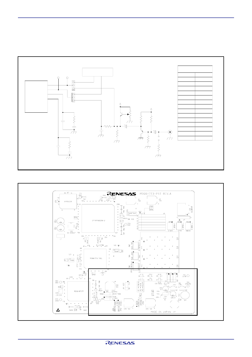
2.9.7 Connection Diagram of Data Slicer
This product has on-board sockets to change parts used for circuits connected to a data slicer. The circuit and the arrangement
of the parts used for each circuit are shown in Figure 2.23 and Figure 2.24, respectively.
Figure 2.23 Connection diagram of circuits connected to the data slicer
Figure 2.24 Arrangement of the parts used for each circuit
C15
C8
R5
C9
C10
C11
R6
SYNCIN
CVIN
LP3
LP4
PER-E
109
108
112
103
JP1
JP2
C14
C12
R13
R7
Q1
R11
R8
VR1
R10
VDDAna
VDDAna
R12
JC1
JP6
C12
C15
C14
560pF
47
μF
47
μF
470
Ω
R7
75
Ω
R12
C10
C11
C9
C8
47pF
0.1
μF
0.1
μF
47pF
R13
R11
R8
R10
10k
Ω
22k
Ω
39k
Ω
470
Ω
Resistance and capacity
Factory-settings
R5
R6
2k
Ω
2k
Ω
Q2
TP4
TP6
User system
- Single-Chip Microcomputer M34551T2-MCU (42 pages)
- M3T-FLX-80NRA (6 pages)
- 70 (162 pages)
- M16C/30P (102 pages)
- PROM Programming Adapter PCA7427G02 (20 pages)
- R0E572110CFK00 (40 pages)
- H8/325 Series (20 pages)
- Single-Chip Microcomputer H8/36079 (27 pages)
- Direct Dummy IC M3T-DIRECT100S (4 pages)
- M3A-2152 (95 pages)
- PCA7755D (6 pages)
- M16C/6N5 (106 pages)
- SH7085 (50 pages)
- QFP-144 (23 pages)
- H8/3834 Series (22 pages)
- RSKM16C62P (3 pages)
- H8/33937 (22 pages)
- Single-Chip Microcomputer H8SX/1622 (5 pages)
- E6000 (29 pages)
- PCA7400 (18 pages)
- PCA4738FF-64 (20 pages)
- SuperH HS7339KCU01HE (43 pages)
- M16C FAMILY (103 pages)
- PCA7412F-100 (20 pages)
- 4513 (210 pages)
- M34551E8FP (16 pages)
- Dummy IC M3T-SSOP36B-450 (4 pages)
- Emulation Pod M30100T3-RPD-E (52 pages)
- Converter Board for M30102 M30102T-PTC (4 pages)
- SH7145 (31 pages)
- HS1653ECN61H (36 pages)
- Converter Board R0E521276CFG00 (4 pages)
- PCA7302E1F-80 (18 pages)
- H8/3814 Series (21 pages)
- H8S/2646 Series (20 pages)
- SuperHTM Family SH7125 Series (40 pages)
- M30262T-PTC (4 pages)
- SH7670 (82 pages)
- H8/3864 Series (20 pages)
- Emulator System M3T-MR100 (306 pages)
- 38K0 (6 pages)
- PLQP0176KB-A (40 pages)
- Direct Dummy IC M3T-DIRECT80S (6 pages)
- PCA4738L-80A (26 pages)
- Converter Board R0E5212BACFG00 (6 pages)