2 each setting, 2) switches – Renesas Emulation Pod M306H7T3-RPD-E User Manual
Page 39
M306H7T3-RPD-E User’s Manual
2. Setup
REJ10J0964-0100 Rev.1.00 August 01, 2005
Page 37 of 88
2.9.2 Each Setting
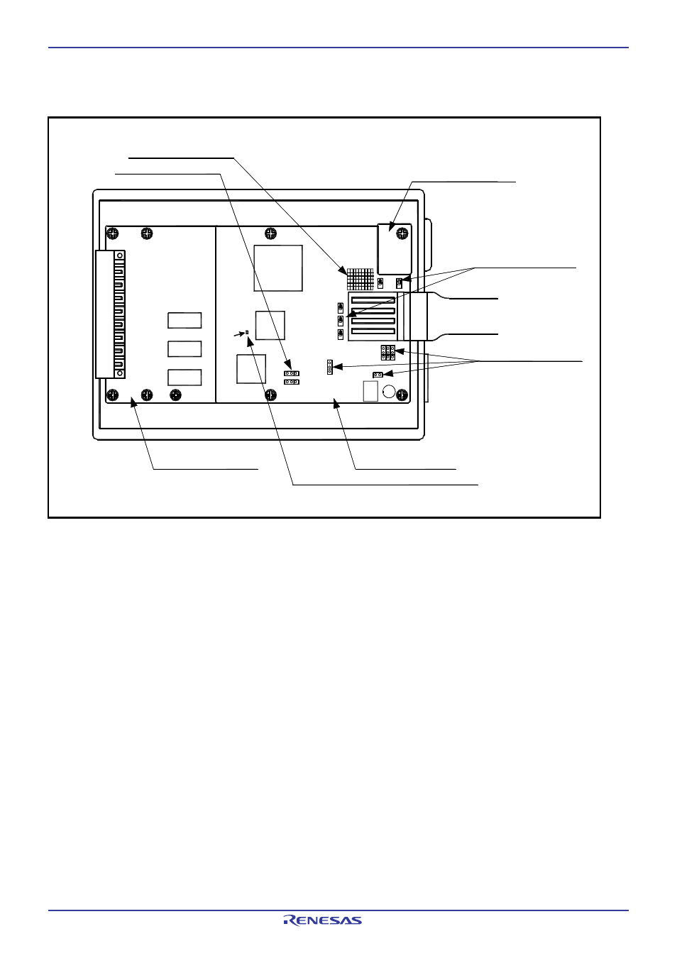
Figure 2.15 shows the positions of each part of this product.
Figure 2.15 Positions of each part
MCU dependent board
Common board
(M30620T3-RPDC)
(1) Oscillator circuit board
(2) Switches
(2) Switches
(3) Socket for mounting
network resister for pullup
(4) Bypass capacitor for A/D converter
SW1
START
CNVss
JP
2
→
CV
IN1
JP
3
→
SY
N
C
IN
JP
4
→
SV
R
EF
JP
5
→
TE
S
T3
ADDAna
V50/
TVDD
(2) Switches
JC1
P87/Xc
in
Xou
t
P
86/
X
c
out
VCC1
(M306H7T3-PRT)
M306H7T3-PRT REV.A
SW2
SW3
SW4
SW5
JP1JP2JP3
JC1_R
JP6
JP4
JP5
JP7
C7
See also other documents in the category Renesas Hardware:
- Single-Chip Microcomputer M34551T2-MCU (42 pages)
- M3T-FLX-80NRA (6 pages)
- 70 (162 pages)
- M16C/30P (102 pages)
- PROM Programming Adapter PCA7427G02 (20 pages)
- R0E572110CFK00 (40 pages)
- H8/325 Series (20 pages)
- Single-Chip Microcomputer H8/36079 (27 pages)
- Direct Dummy IC M3T-DIRECT100S (4 pages)
- M3A-2152 (95 pages)
- PCA7755D (6 pages)
- M16C/6N5 (106 pages)
- SH7085 (50 pages)
- QFP-144 (23 pages)
- H8/3834 Series (22 pages)
- RSKM16C62P (3 pages)
- H8/33937 (22 pages)
- Single-Chip Microcomputer H8SX/1622 (5 pages)
- E6000 (29 pages)
- PCA7400 (18 pages)
- PCA4738FF-64 (20 pages)
- SuperH HS7339KCU01HE (43 pages)
- M16C FAMILY (103 pages)
- PCA7412F-100 (20 pages)
- 4513 (210 pages)
- M34551E8FP (16 pages)
- Dummy IC M3T-SSOP36B-450 (4 pages)
- Emulation Pod M30100T3-RPD-E (52 pages)
- Converter Board for M30102 M30102T-PTC (4 pages)
- SH7145 (31 pages)
- HS1653ECN61H (36 pages)
- Converter Board R0E521276CFG00 (4 pages)
- PCA7302E1F-80 (18 pages)
- H8/3814 Series (21 pages)
- H8S/2646 Series (20 pages)
- SuperHTM Family SH7125 Series (40 pages)
- M30262T-PTC (4 pages)
- SH7670 (82 pages)
- H8/3864 Series (20 pages)
- Emulator System M3T-MR100 (306 pages)
- 38K0 (6 pages)
- PLQP0176KB-A (40 pages)
- Direct Dummy IC M3T-DIRECT80S (6 pages)
- PCA4738L-80A (26 pages)
- Converter Board R0E5212BACFG00 (6 pages)