72
µPD750008 USER'S MANUAL
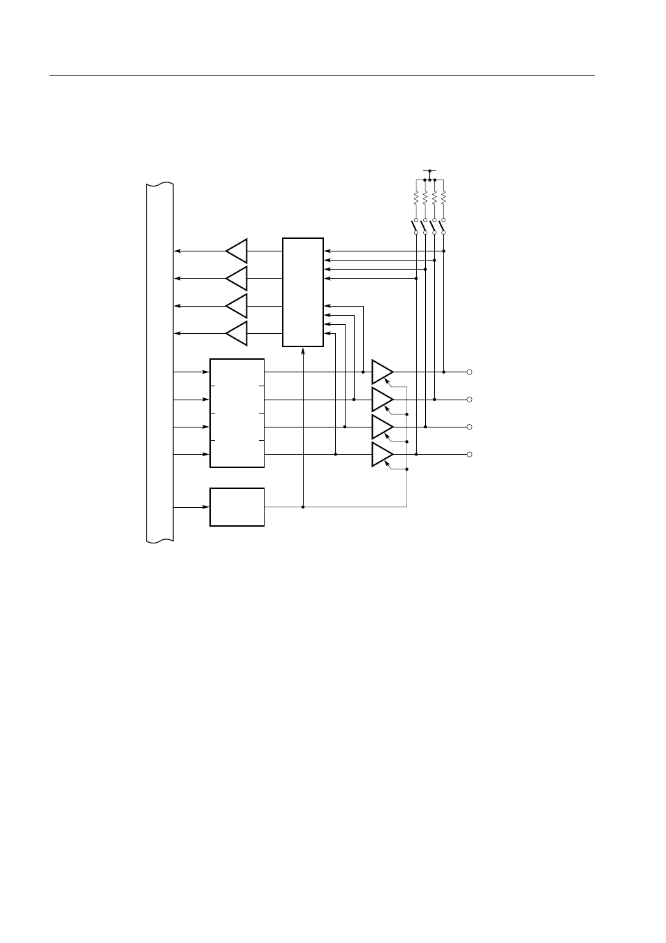
Figure 5-5. Configurations of Ports 4 and 5
Internal bus
Input buffer
MPX
V
DD
Pm0
Pm1
Pm2
Pm3
PMm = 0
PMm = 1
PMm
Output
latch
Pull-up resistor
N-ch open-drain
output buffer
Corresponding bits of port mode
register group B (m = 4, 5)
(Mask option)