NEC PD750008 User Manual
Page 90
70
µPD750008 USER'S MANUAL
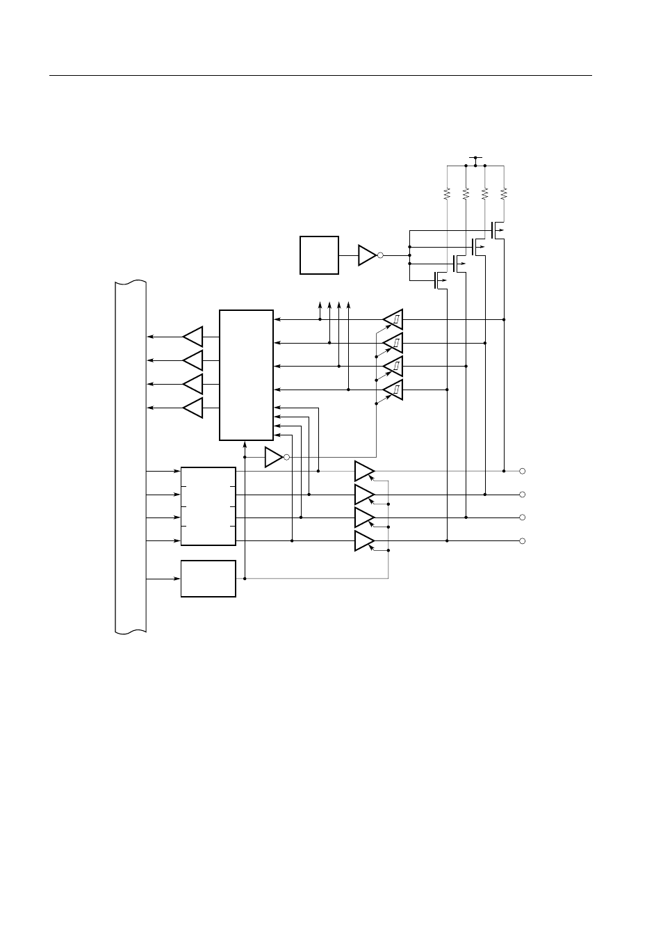
Figure 5-3. Configurations of Ports 2 and 7
Note For port 7 only
M
P
X
Input buffer
PMm = 0
Key interrupt
Note
Output
latch
PMm
Bits 2 and 7 of port mode
register group B (m = 2, 7)
Output buffer
Internal bus
Pm0
Pm1
Pm2
Pm3
Bit m of
POGA
Pull-up
resistor
V
DD
P-ch
Input buffer with
hysteresis
Note
PMm = 1