NEC PD750008 User Manual
Page 182
162
µPD750008 USER'S MANUAL
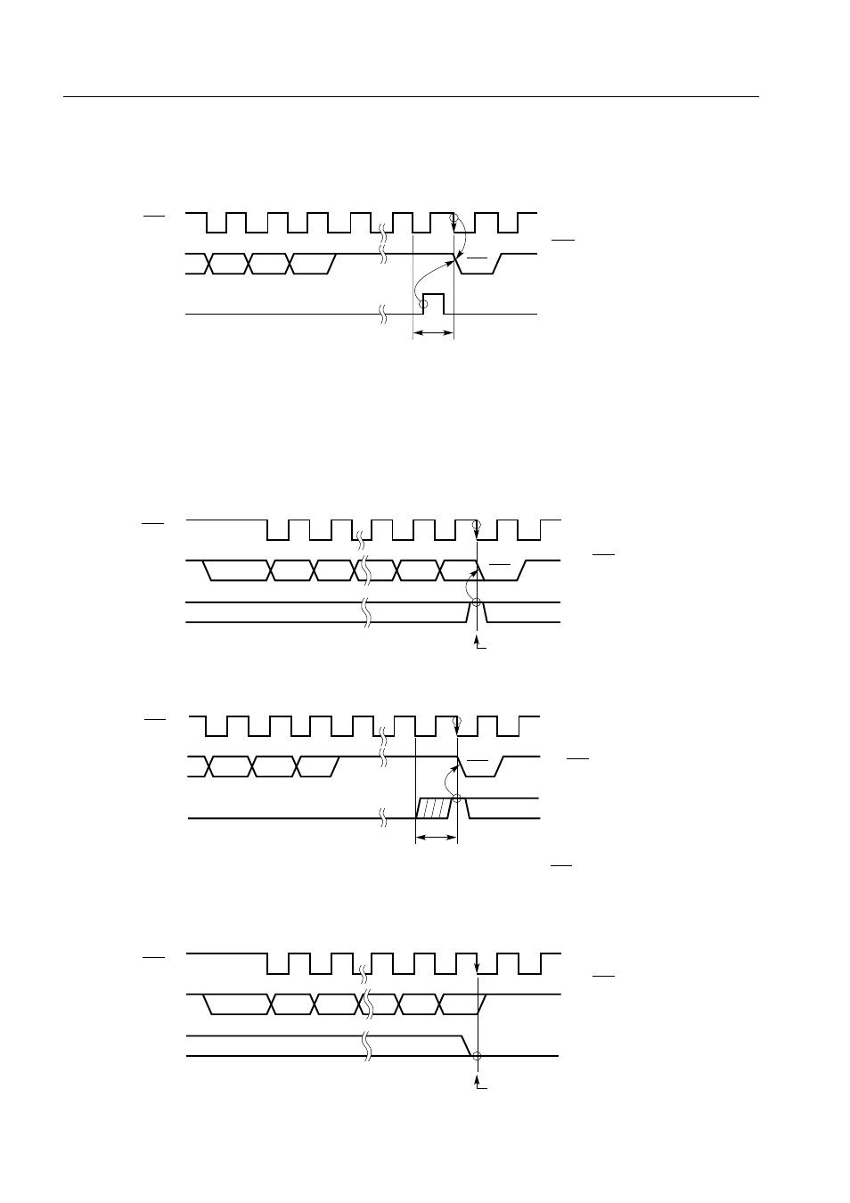
Figure 5-62. Operation of ACKT
Caution Do not set the ACKT until the transfer is completed.
Figure 5-63. Operation of ACKE (1/2)
(a) When ACKE = 1 at time of transfer completion
(b) When ACKE is set after transfer completion
(c) When ACKE = 0 at time of transfer completion
SCK
6
7
8
9
D2 D1 D0
SB0, SB1
ACK
ACKT
ACK signal is output during the first clock
cycle immediately after ACKT is set.
When set during this period
When ACKT is set after transfer completion
SCK
1
2
7
8
D7 D6 D2 D1
SB0, SB1
D0
9
ACK
ACKE
When ACKE = 1 at this point
The ACK signal is output
during the ninth clock
cycle.
SCK
6
7
8
9
D2 D1
D0
SB0, SB1
ACK
ACKE
The ACK signal is output
during the first clock cycle
immediately after ACKE is set.
When ACKE is set during this period and ACKE = 1 at
the falling edge of the next SCK
SCK
1
2
7
8
D7 D6 D2
D1
SB0, SB1
D0
9
ACKE
The ACK signal is not
output.
When ACKE = 0 at this point