NEC PD750008 User Manual
Page 139
119
CHAPTER 5 PERIPHERAL HARDWARE FUNCTIONS
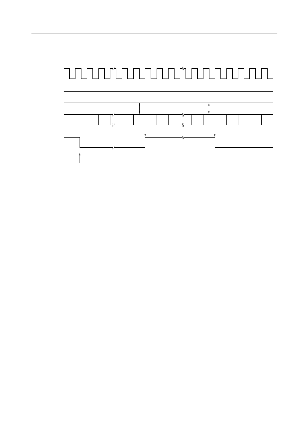
Figure 5-36. Count Operation Timing
(4) Applications of the timer/event counter
(a) Timer/event counter is used as an interval timer that generates interrupts at intervals of 30 ms.
• The high-order four bits of the mode register are set to 0100B to select maximum set time 43.7 ms
(at f
X
= 6.00 MHz).
• The low-order four bits of the mode register are set to 1100B.
• The modulo register is set to the following value:
30 ms/171 µs = 175.4
=
.
.
AFH
SEL
MB15
MOV
XA,#0AEH
MOV
TMOD0,XA
; Set the modulo register
MOV
XA,#01001100B
MOV
TM0,XA
; Set the mode register and start the timer
EI
; Enable an interrupt
EI
IET0
; Enable a timer interrupt
Remark In this application, the TI0 pin can be used as an input pin.
(b) An interrupt is caused when the number of pulses (active high) applied to the TI0 pin reaches
100.
• The high-order four bits of the mode register are set to 0000 to select the rising edge.
• The low-order four bits of the mode register are set to 1100B.
• The modulo register is set to 99 = 100 – 1.
Modulo register
(TMODn)
Count register
(Tn)
TOUT F/F
Count pulse(CP)
Reset
Timer start indication
Match
Match
n
0
1
2
n–1
0
1
2
n
n–1
0
1
2
n
3
4