Release of the standby modes – NEC PD750008 User Manual
Page 237
217
CHAPTER 7 STANDBY FUNCTION
Caution
2. Reset all the interrupt request flags before setting the standby mode. If an interrupt
source whose interrupt request flag and interrupt enable flag are both set exists, the
initiated standby mode is released immediately after it is set (see Figure 6-1). When
the STOP mode is set, however, the µPD750008 enters the HALT mode immediately
after the STOP instruction is executed, then returns to the operation mode after the
wait time specified by the BTM register has elapsed.
7.2 RELEASE OF THE STANDBY MODES
The STOP mode and HALT mode are released by a RESET signal or the generation of an interrupt request
signal that is enabled with the interrupt enable flag. Figure 7-1 shows how the STOP and HALT modes are
released.
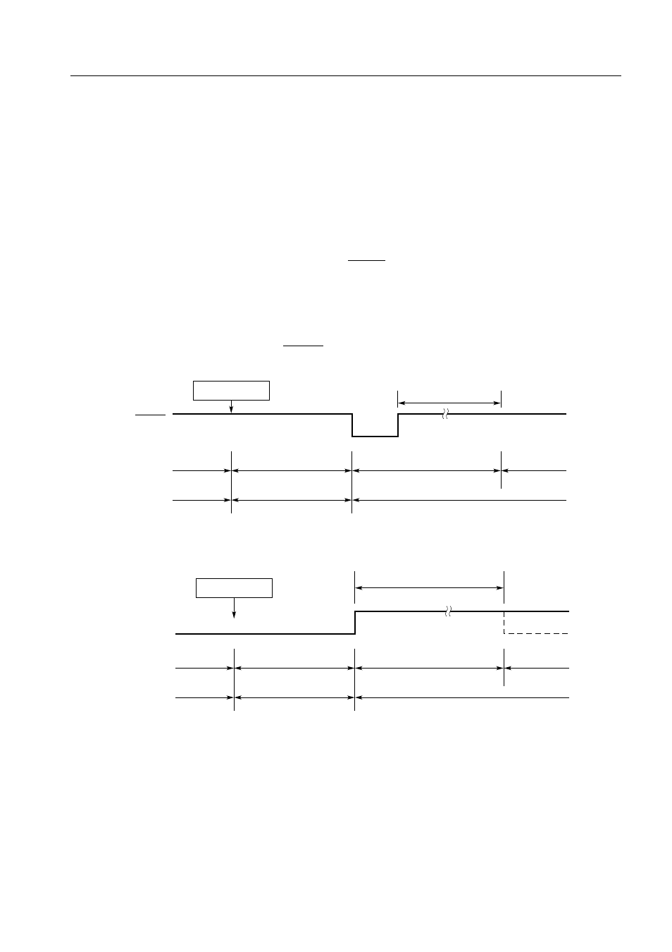
Figure 7-1. Standby Mode Release Operation (1/2)
(a) Release of the STOP mode by RESET signal
(b) Release of the STOP mode by the occurrence of an interrupt
Note The following two wait times can be selected by a mask option:
2
17
/f
X
(21.8 ms at 6.00 MHz, 31.3 ms at 4.19 MHz)
2
15
/f
X
(5.46 ms at 6.00 MHz, 7.81 ms at 4.19 MHz)
However, the µPD75P0016 does not have a mask option and its wait time is fixed to 2
15
/f
X
.
Remark The dashed line indicates the case where the interrupt request that releases the standby mode
is accepted.
STOP instruction
Standby
release
signal
Clock
Operating
mode
STOP mode
HALT mode
Operating
mode
No oscillation
Oscillation
Oscillation
Wait
(Time set by BTM)
*
STOP instruction
Wait
RESET
signal
Clock
Operating
mode
STOP mode
HALT mode
Operating
mode
No oscillation
Oscillation
Oscillation
Note