NEC PD750008 User Manual
Page 204
184
µPD750008 USER'S MANUAL
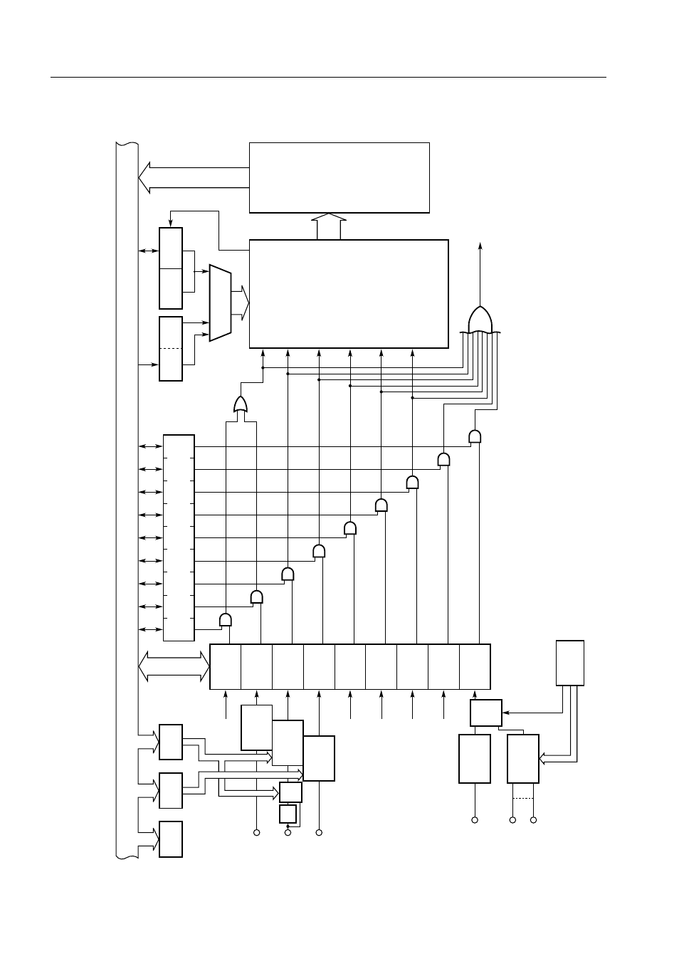
Figure 6-1. Block Diagram of Interrupt Control Circuit*
2
IM2
14
IRQBT
IRQ4
IRQ0
IRQ1
IRQCSI
IRQT0
IRQT1
IRQW
IRQ2
INTBT
INT4/P00
INT0/P10
INT1/P11
INTCSI
INTT0
INTT1
INTW
INT2/P12
Both-edge
detection
circuit
IM0
Edge
detection
circuit
Edge
detection
circuit
Rising edge
detection
circuit
Falling edge
detection
circuit
KR0/P60
KR7/P73
Selec-
tor
IM2
Interrupt enable flag (IExxx)
IPS
IST0
IME
Priority control circuit
Decoder
VRQn
Vector table
address
generator
Standby release signal
Internal bus
Selec-
tor
Note
IM1
Note
Noise eliminator (when the noise eliminator is selected, standby mode cannot be released.)
IST1