NEC PD750008 User Manual
Page 153
133
CHAPTER 5 PERIPHERAL HARDWARE FUNCTIONS
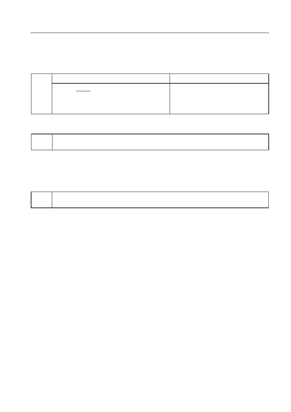
Figure 5-41. Format of Serial Bus Interface Control Register (SBIC) (3/3)
Bus release detection flag (R)
RELD
Condition for being cleared (RELD = 0)
Condition for being set (RELD = 1)
<1> The transfer start instruction is executed.
The bus release signal (REL) is detected.
<2> The RESET signal is generated.
<3> CSIE = 0 (Figure 5-40)
<4> SVA does not match SIO when an address is
received.
Command trigger bit (W)
CMDT
Control bit for command signal (CMD) trigger output. By setting CMDT = 1, the SO latch is
cleared. Then the CMDT bit is automatically cleared to 0.
Caution Never clear SB0 (or SB1) during serial transfer. Be sure to clear SB0 (or SB1) before or
after serial transfer
Bus release trigger bit (W)
RELT
Control bit for bus release signal (REL) trigger output.
By setting RELT = 1, the SO latch is set to 1. Then the RELT bit is automatically cleared to 0.
Caution Never clear SB0 (or SB1) during serial transfer. Be sure to clear SB0 (or SB1) before or
after serial transfer.
Examples 1. A command signal is output.
SEL
MB15
; or CLR1 MBE
SET1
CMDT
2. RELD and CMDD are tested to identify the types of received data and the types of processing
accordingly. By setting WUP = 1, this interrupt routine is processed only when an address
match is found.
SEL
MB15
SKF
RELD
; RELD test
BR
!ADRS
SKT
CMDD
; CMDD test
BR
!DATA
BR
!CMD
CMD: ...................... ; Command analysis
DATA: ..................... ; Data processing
ADRS: .................... ; Address decode