NEC PD750008 User Manual
Page 45
2 5
CHAPTER 3 FEATURES OF THE ARCHITECTURE AND MEMORY MAP
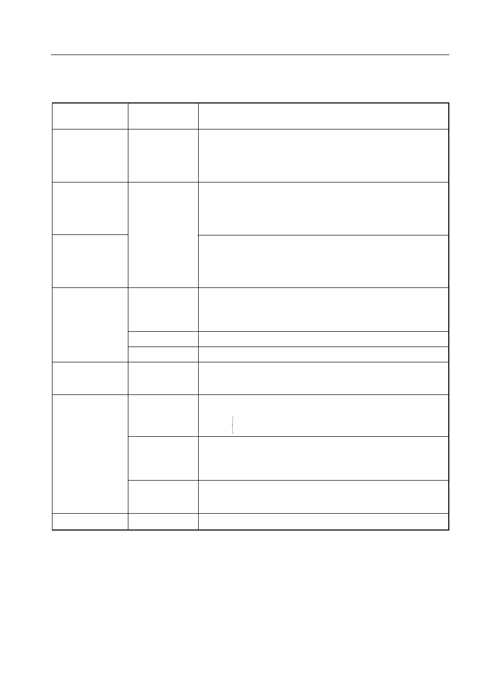
Table 3-1. Addressing Modes
Addressing mode
Representation
Specified address
format
1-bit direct
mem.bit
Bit specified by bit at the address specified by MB and mem.
addressing
• When MBE = 0 and
mem = 00H-7FH,
MB = 0
mem = 80H-FFH,
MB = 15
• When MBE = 1,
MB = MBS
4-bit direct
mem
Address specified by MB and mem.
addressing
• When MBE = 0 and
mem = 00H-7FH,
MB = 0
mem = 80H-FFH,
MB = 15
• When MBE = 1,
MB = MBS
8-bit direct
Address specified by MB and mem (mem: even address).
addressing
• When MBE = 0 and
mem = 00H-7FH,
MB = 0
mem = 80H-FFH,
MB = 15
• When MBE = 1,
MB = MBS
4-bit register
@HL
Address specified by MB and HL.
indirect
@HL+
In this case, MB = MBE·MBS
addressing
@HL–
HL+ automatically increments the L register after addressing.
HL– automatically decrements the L register after addressing.
@DE
Address specified by DE in memory bank 0
@DL
Address specified by DL in memory bank 0
8-bit register
@HL
Address specified by MB and HL. (Contents of the L register is
indirect
an even address.)
addressing
In this case, MB = MBE·MBS
Bit
fmem.bit
Bit specified by bit at the address specified by fmem.
manipulation
In this case,
addressing
fmem =
FB0H-FBFH (interrupt-related hardware)
FF0H-FFFH (I/O ports)
pmem.@L
Bit specified by the low-order two bits of the L register
at the address specified by the high-order 10 bits of pmem and the
high-order two bits of the L register.
In this case, pmem = FC0H-FFFH
@H+mem.bit
Bit specified by bit at the address specified by MB, H, and the low-
order four bits of mem.
In this case, MB = MBE·MBS
Stack addressing
—
Address specified by the SP in memory bank selected by the SBS