NEC PD750008 User Manual
Page 168
148
µPD750008 USER'S MANUAL
(3) Serial clock selection
To select the serial clock, manipulate bits 0 and 1 of serial operation mode register (CSIM). The serial
clock can be selected out of the following four clocks:
Table 5-8. Serial Clock Selection and Application (In the Two-Wire Serial I/O Mode)
Mode register
Serial clock
Timing for shift register R/W and
Application
CSIM
CSIM
Source
Masking of
start of serial transfer
1
0
serial clock
0
0
External
Automatically
<1> In the operation halt mode
Slave CPU
SCK
masked when
(CSIE = 0)
0
1
TOUT
8-bit data
<2> When the serial clock is
Arbitrary-speed
flip-flop
transfer is
masked after 8-bit transfer
serial transfer
completed
<3> When SCK is high
1
0
f
X
/2
6
Low-speed
1
1
serial transfer
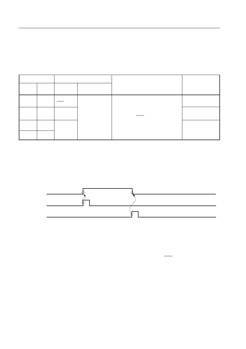
(4) Signals
Figure 5-49 shows operations of RELT and CMDT.
Figure 5-49. Operations of RELT and CMDT
(5) Transfer start
Serial transfer starts by writing transfer data into shift register (SIO), provided that the following two
conditions are satisfied:
• The serial interface operation enable/disable specification bit (CSIE) is set to 1.
• The internal serial clock is not operating after 8-bit serial transfer, or SCK is high.
Cautions 1. Setting CSIE to 1 after writing data to the shift register does not start transfer.
2. When data is received, the N-ch transistor must be turned off, so FFH must be
written to SIO beforehand.
When eight bits have been transferred, serial transfer automatically terminates setting the interrupt
request flag (IRQCSI).
SO latch
RELT
CMDT