NEC PD750008 User Manual
Page 233
213
CHAPTER 6 INTERRUPT AND TEST FUNCTIONS
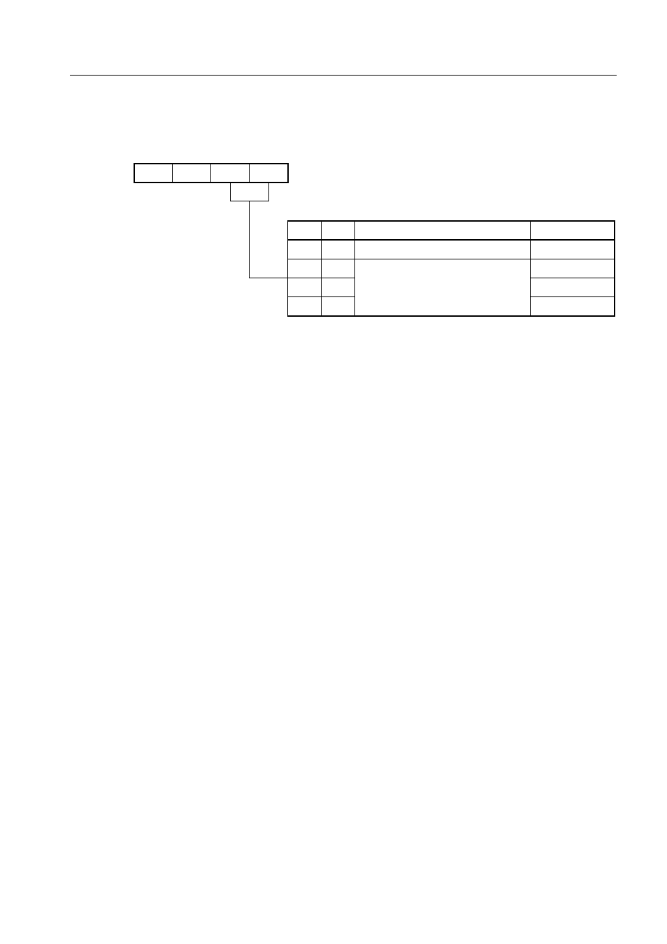
Figure 6-11. Format of INT2 Edge Detection Mode Register (IM2)
Cautions 1. When the edge detection mode register is modified, test request flags may be set in
some cases. So, disable test inputs before modifying the edge detection mode
register. Then, clear the test request flags using a CLR1 instruction before enabling
test inputs.
2. When a low-level signal is applied to any of the pins subjected to falling edge detection,
IRQ2 is not set when a falling edge is detected on another pin.
0
0
IM21
IM20
FB6H
IM2
IM21
0
0
1
1
IM20
0
1
0
1
Specifies rising edge of INT2 pin input.
Interrupt input pin
INT2 (1)
KR4 - KR7 (4)
KR2 - KR7 (6)
KR0 - KR7 (8)
Specifies falling edge of any of KRx pin
inputs.
INT2 interrupt source
0
1
2
3
Symbol
Address