NEC PD750008 User Manual
Page 211
191
CHAPTER 6 INTERRUPT AND TEST FUNCTIONS
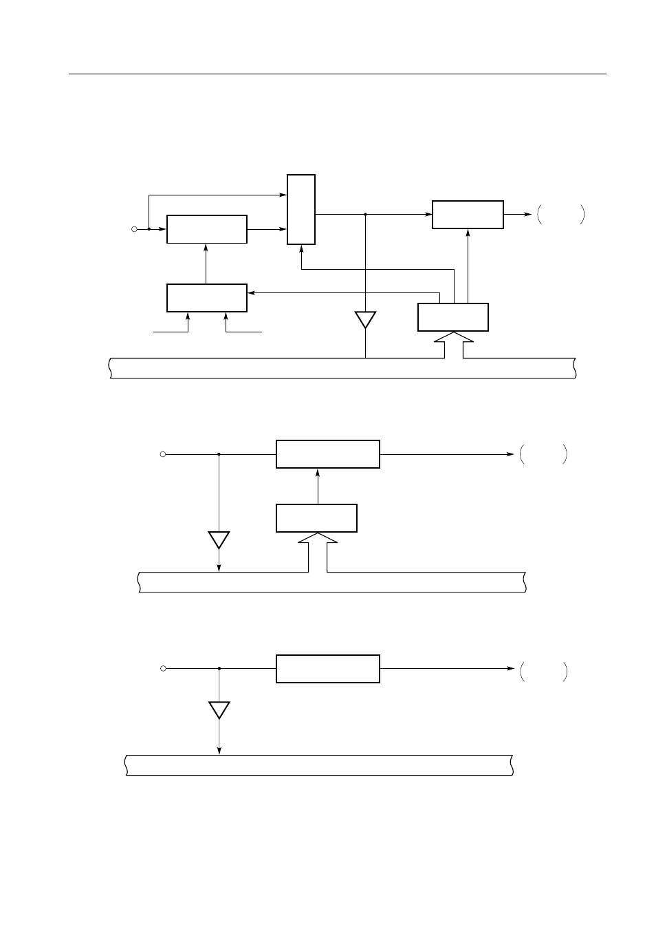
Figure 6-4. Configurations of the INT0, INT1, and INT4 Circuits
(a) Configuration of the INT0 circuit
(b) Configuration of the INT1 circuit
(c) Configuration of the INT4 circuit
INT0/P10
IM00, IM01
Internal bus
IM0
4
Edge detection
circuit
IRQ0
set signal
INT0
Input buffer
Detection edge
specification
Sampling clock selection
Noise eliminator
Selector
Selector
IM02
IM03
f
X
/64
Φ
INT1/P11
IM10
Internal bus
IM1
4
Edge detection circuit
IRQ1
set signal
INT1
Input buffer
Detection edge specification
INT4/P00
Internal bus
Both-edge
detection circuit
Input buffer
IRQ4
set signal
INT4