NEC PD750008 User Manual
Page 30
1 0
µPD750008 USER'S MANUAL
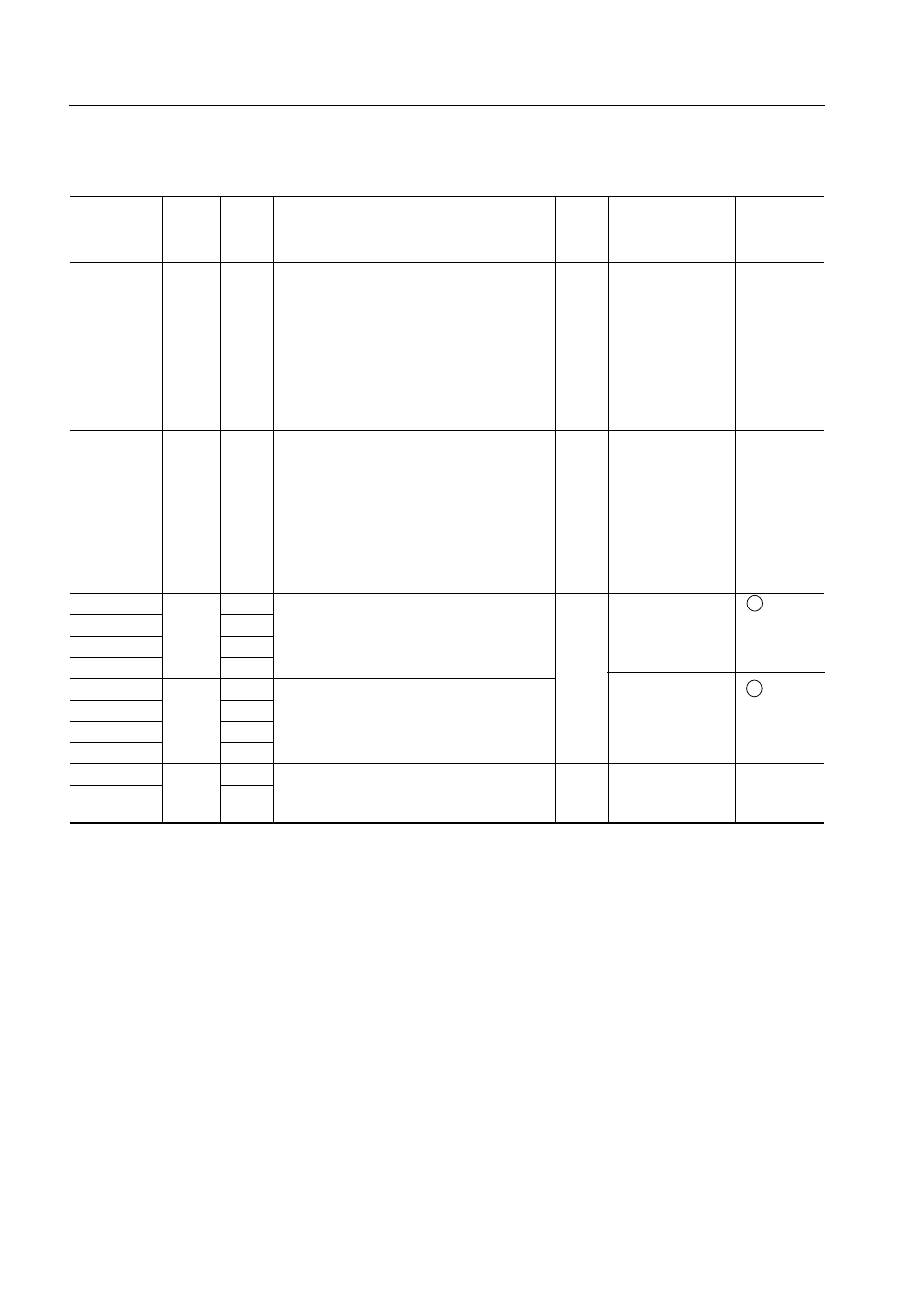
Table 2-1. Digital I/O Port Pins (2/2)
Input
Also
8 bit
Upon
I/O
Pin
output
used
Function
circuit
as
I/O
reset
type
Note 1
P40-
I/O
—
N-ch open-drain 4-bit I/O port (PORT4).
O
High level (when
M-D
P43
Note 2, 4
Withstand voltage is 13 V in open-drain
a pull-up resistor
(M-E)
Note 3
mode.
is provided) or
A pull-up resistor can be provided bit
high impedance
by bit (mask option)
Note 5
.
Data input/output pins for writing/
verifying (lower 4 bits of program
memory (PROM).
P50-
I/O
—
N-ch open-drain 4-bit I/O port (PORT5).
O
High level (when
M-D
P53
Note 2, 4
Withstand voltage is 13 V in open-drain
a pull-up resistor
(M-E)
Note 3
mode.
is provided) or
A pull-up resistor can be provided bit
high impedance
by bit (mask option)
Note 5
.
Data input/output pins for writing/
verifying (higher 4 bits of program
memory (PROM).
P60
I/O
KR0
Programmable 4-bit I/O port (PORT6).
O
Input
F -A
P61
KR1
I/O can be specified bit by bit.
P62
KR2
Built-in pull-up resistors can be
P63
KR3
connected by software in units of 4 bits.
P70
I/O
KR4
4-bit I/O port (PORT7).
Input
F -A
P71
KR5
Built-in pull-up resistors can be
P72
KR6
connected by software in units of
P73
KR7
4 bits.
P80
I/O
—
2-bit input port (PORT8).
x
Input
E-B
P81
—
Built-in pull-up resistors can be
connected by software in units of 2 bits.
Notes 1. I/O circuits enclosed in circles have a Schmitt-triggered input.
2. An LED can be driven directly.
3. ( ): µPD75P0016
4. When pull-up resistors that can be specified with the mask option are not
incorporated (when pins are used as N-ch open-drain input ports), the input leak low
current increases when an input instruction or bit operation instruction is executed.
5. These pins of the µPD75P0016 are not provided with pull-up resistors by mask option, and are
always open.
*
*
*
*
*
*