Connection and setup – Kathrein UFS 922 si User Manual
Page 9
9
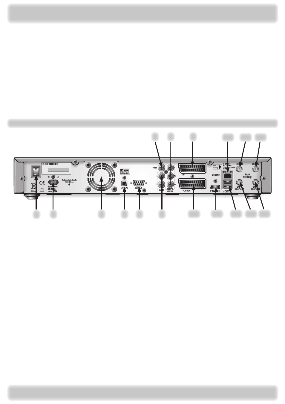
Connection and setup
View of rear panel
~
1
10
2
3
4
5
6
7
8
9
11
12
16
13 14 15
17
1.
On/Off switch (disconnection from the mains)
.
Mains power cable
.
Fan
4. Optical data stream output (SPDIF/Sony Philips
Digital Interface Format) for Dolby Digital AC audio
5.
Data interface (for service only)
6. Audio outputs (L/R) - cinch sockets
7.
Video output (composite colour)
8. 3 x Cinch connections for component outputs YUV
labelled = Y/Pb/Pr
9. Scart socket for TV connection
10. Scart socket for VCR/AUX connection
11. HDMI connection
1. Network connection (Ethernet)
13. 2 x USB 2.0 ports (USB-A connectors)
14. LNB 2 loop-through output
15. LNB 1 loop-through output
16. LNB input
17. LNB 1 input
Topic
Page
View of rear panel ........................................................................................................................................................... 9
View of front panel (flap folded down) .......................................................................................................................... 10
Connecting the unit (Sat-IF connections) ..................................................................................................................... 10
Information about antenna connection and loop-through mode .................................................................................... 11
Connection example ..................................................................................................................................................... 1
TV and VCR connection ............................................................................................................................................... 1
Audio connection .......................................................................................................................................................... 1
Optical digital output ..................................................................................................................................................... 1
Inserting batteries into the remote control .................................................................................................................... 1
First installation ............................................................................................................................................................ 14