Figure 5-6, Pcb module connectors – KVH Industries TracVision G8 User Manual
Page 96
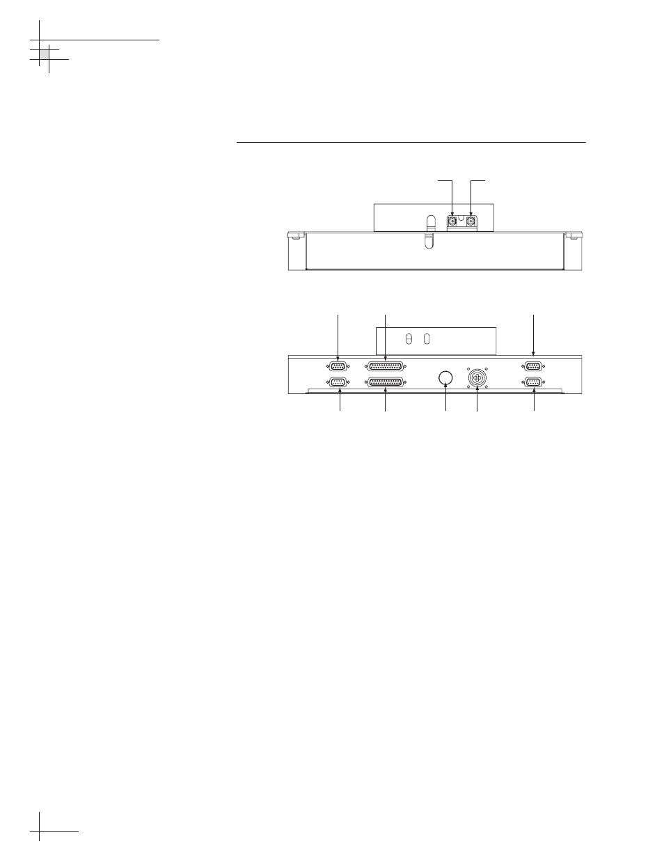
7. Reconnect the cables that you removed in Step 4. Be
sure to reconnect all cables in their proper positions.
Figure 5-6 shows the proper connector assignments.
Figure 5-6
PCB Module Connectors
8. Apply power to the antenna unit.
9. Using the PC connected to the maintenance port, type
HALT then press Enter.
10. Type DEBUGON then press Enter.
11. Type =TVG8SS then press Enter.
12. Type =SERNUM, number> = the serial number you recorded in Step 2. 13. Type ZAP then press Enter to restart/reinitialize the system. 14. Calibrate the antenna gyros as explained in “Calibrating the Gyros” on page 105. 15. Reinstall your selected satellites as explained in Section 2.7, “Installing Satellites Using the MCU,” on page 42. 54-0198 100 TracVision G8 Owner’s Manual - Guide to Technical Information POWER ELEVATION GYRO INTERNAL SENSOR SKEW MOTOR ELEVATION & AZIMUTH MOTORS AZIMUTH/ROLL GYRO LIMIT SWITCHES FUSE Limit Switches Internal Sensor Azimuth Gyro Elevation Gyro Power Elevation & Azimuth Motors Skew Motor Fuse To LNB BOTTOM TOP RF1 From IRD
Then press Enter.