KVH Industries TracVision G8 User Manual
Page 31
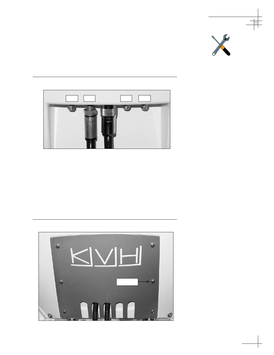
11. Using a
9
⁄
16
" wrench, connect the RF cable(s) from
belowdecks to the baseplate. If you connect more than
one RF cable, label both ends of each RF cable to match its
antenna baseplate connector (RF1, RF2, RF3, or RF4).
Figure 2-9 shows an RF cable connected to the RF1
connector.
Figure 2-9
Connecting the RF1 Cable
12. Route the other ends of the data/power and RF cables
belowdecks (if mounting the antenna to the deck, route
the cables into the cable access hole that you cut out in
Step 4).
13. Place the rear logo plate over the cables, so that each cable
exits the proper opening (see Figure 2-10). Using the six
M4 screws supplied in the kitpack, attach the logo plate to
the baseplate as shown in Figure 2-10.
Figure 2-10
Attaching the Logo Plate
Installation
54-0198
29
Do NOT use teflon gel on the cable
fittings as it reduces signal strength
at higher frequencies.
RF3
RF1
RF2
RF4
M4 Screw