KVH Industries TracVision G8 User Manual
Page 30
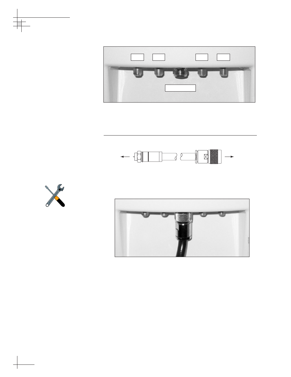
Figure 2-6
Baseplate Connectors
10. Connect the N-type connector end of the data/power
cable to the baseplate, as shown in Figures 2-7 and 2-8.
Figure 2-7
Data/power Cable Connectors
Figure 2-8
Connecting the Data/Power Cable
54-0198
28
TracVision G8 Owner’s Manual - Guide to Technical Information
RF3
RF1
RF2
RF4
Data/Power
F-type Connector
N-type Connector
To MCU
To Antenna
Be sure to properly align the
data/power cable with the
baseplate connector before
tightening. Connecting the cable at
an angle may damage the cable’s
center tines.