18 - replacing the lnb/feed tube assembly, 18 replacing the lnb/feed tube assembly, Figure 5-33 – KVH Industries TracVision G8 User Manual
Page 114: Figure 5-34, Lnb (linear quad version shown), Skew motor cable connector on pcb module, Using a
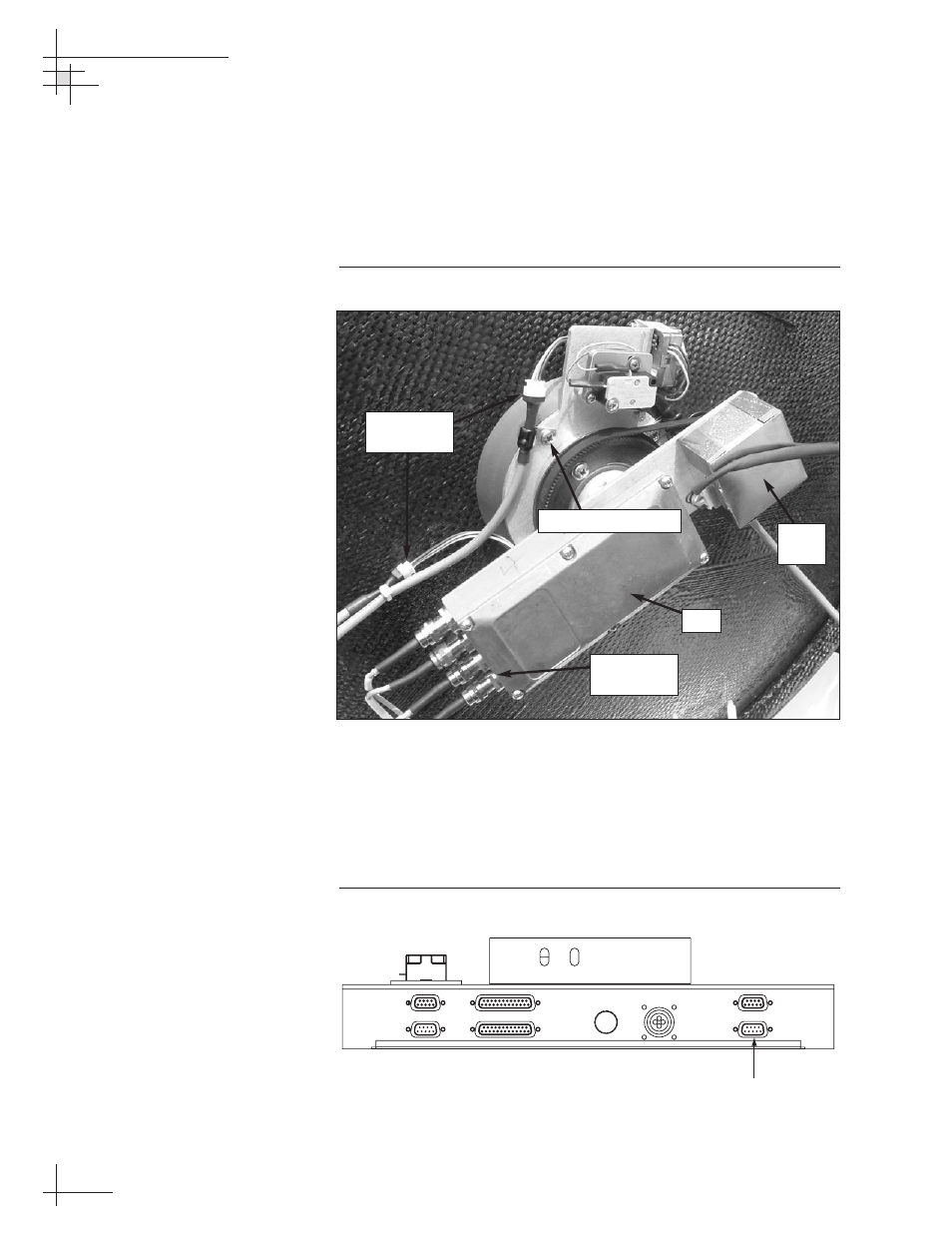
5.18 Replacing the LNB/Feed Tube
Assembly
1. Using a
7
⁄
16
" wrench, carefully disconnect the RF cables
from the LNB.
Figure 5-33
LNB (Linear Quad version Shown)
2. Disconnect the azimuth and elevation gyro cables from
the in-line connectors.
3. Linear quad LNB systems only:
Disconnect the skew motor cable from the PCB module
(see Figure 5-34).
Figure 5-34
Skew Motor Cable Connector on PCB Module
54-0198
118
TracVision G8 Owner’s Manual - Guide to Technical Information
POWER
ELEVATION GYRO
INTERNAL SENSOR
SKEW MOTOR
ELEVATION & AZIMUTH MOTORS
AZIMUTH/ROLL GYRO
LIMIT SWITCHES
FUSE
Skew Motor
Cable Connector
RF Cable
Connectors
LNB
Skew
Motor
#8-32 Screws (x 4)
Gyro Cable
Connectors