Samsung SMG-3200 User Manual
Page 22
2-4
Chapter 2
System Boards
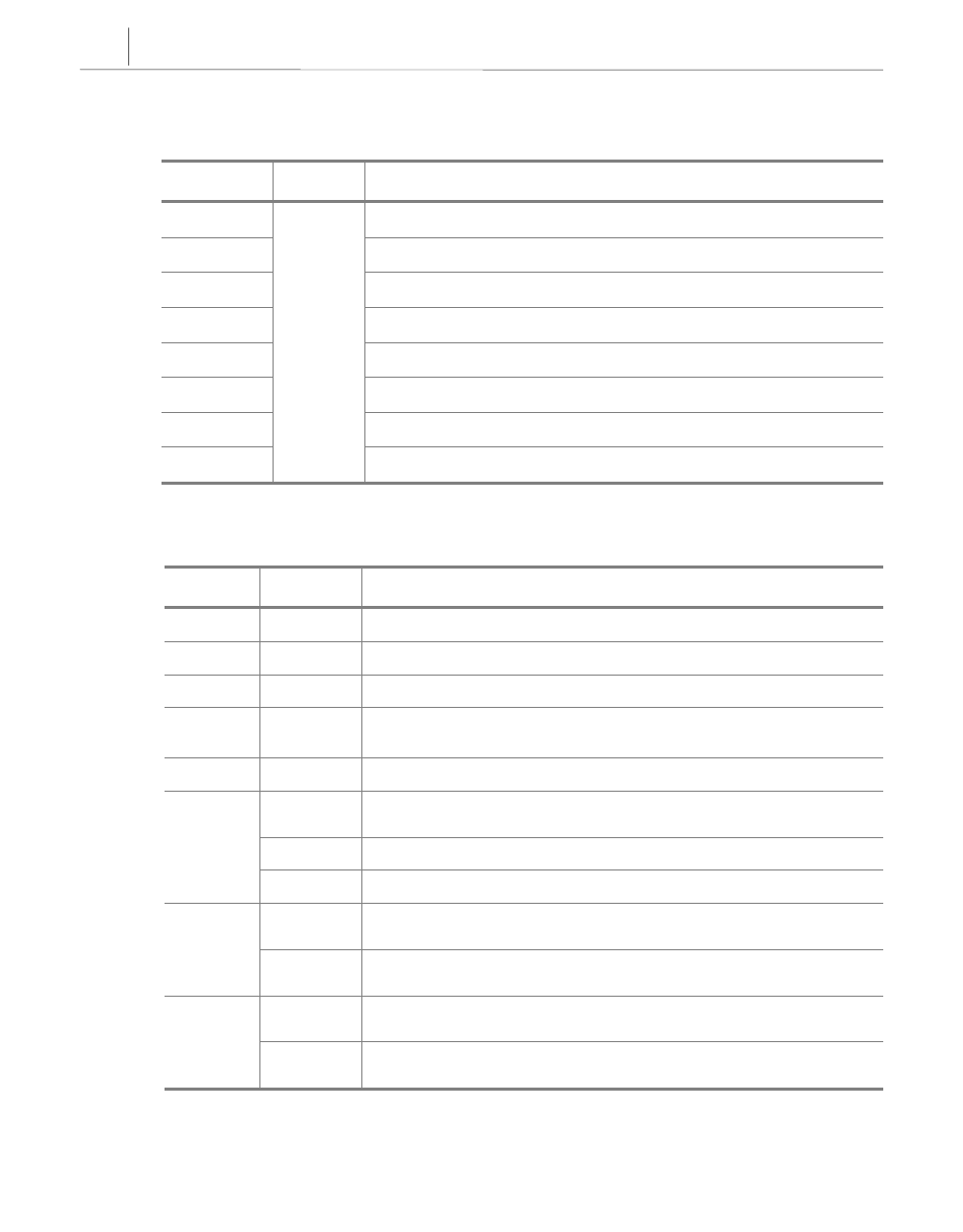
❹ LED Indicators
LED
LED
LED
LED
Color
Color
Color
Color
Description
Description
Description
Description
L1
LED blinks during system initialization.
L2
LED blinks during normal system operation.
PWR
LED is on when power is normally supplied to system.
OPER
LED blinks during system software operation.
LAN TX
LED blinks during data transmission through LAN port.
LAN RX
LED blinks during data reception through LAN port.
E1 SYNC
LED is on if D-TRK clock synchronization fails.
E1 LOS
Green
LED is on if D-TRK signal is missing.
r DIP Switch
Switch
Switch
Switch
Switch
Default
Default
Default
Default
Description
Description
Description
Description
S1
OFF
Reserved
S2
OFF
Reserved
S3
OFF
Reserved
S4
OFF
For D-TRK clock signal input, set to ON. Set to ON state during
an offline test (used in factory)
S5
OFF
For D-TRK signal data input, set to ON.
ON
OFF
1, 2 : BPS
0, 1 : 8bit operation
ON
3 : IP
0 : MSR[IP] initial value is one
S6
OFF
4 : EARP
0 : Internal operation
OFF
ON
Reserved.
S7
OFF
OFF
3, 4 : ISB
1, 0 : Base address 0xFF000000
ON
ON
Reserved.
S8
ON
ON
3, 4 : DBPC
0, 0 : Debug Port Configuration