Module configuration and status registers, Module configuration and status registers -33 – Motorola MVME2300 Series User Manual
Page 57
ISA Local Resource Bus
http://www.motorola.com/computer/literature
1-33
1
The NVRAM/RTC Address Strobe 0 register latches the lower 8 bits of the
address and the NVRAM/RTC Address Strobe 1 register latches the upper
5 bits of the address.
The NVRAM and RTC are accessed through the above three registers.
When accessing an NVRAM/RTC location, follow this procedure:
1. Write the low address (A7-A0) of the NVRAM to the
NVRAM/RTC STB0 register,
2. Write the high address (A15-A8) of the NVRAM to the
NVRAM/RTC STB1 register, and
3. Then read or write the NVRAM/RTC Data Port.
Refer to the M48T59 Data Sheet for additional details and programming
information.
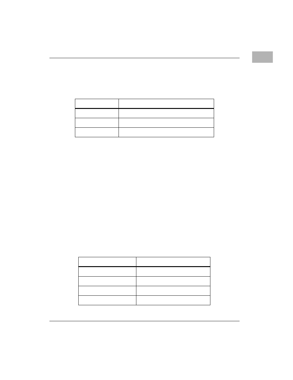
Module Configuration and Status Registers
Four registers provide the configuration and status information about the
board. These registers are listed in the following table:
Table 1-17. M48T59/559 Access Registers
PCI I/O Address
Function
0000 0074
NVRAM/RTC Address Strobe 0 (A7 - A0)
0000 0075
NVRAM/RTC Address Strobe 1 (A15 - A8)
0000 0077
NVRAM/RTC Data Register
Table 1-18. Module Configuration and Status Registers
PCI I/O Address
Function
0000 0800
CPU Configuration Register
0000 0802
Base Module Feature Register
0000 0803
Base Module Status Register
0000 08C0 - 0000 08C1
Seven-Segment Display Register