Timer vector/priority registers, Timer vector/priority registers -79 – Motorola MVME2300 Series User Manual
Page 149
Raven Interrupt Controller
http://www.motorola.com/computer/literature
2-79
2
CI
Count Inhibit. Setting this bit to 1 inhibits counting for
this timer. Setting the bit to 0 allows counting to proceed.
BC
Base Count. This field contains the 31-bit count for this
timer. When a value is written into this register and the CI
bit transitions from a 1 to a 0, the value is copied into the
corresponding Current Count register and the toggle bit in
the Current Count register is cleared. When the timer
counts down to zero, the Current Count register is
reloaded from the Base Count register.
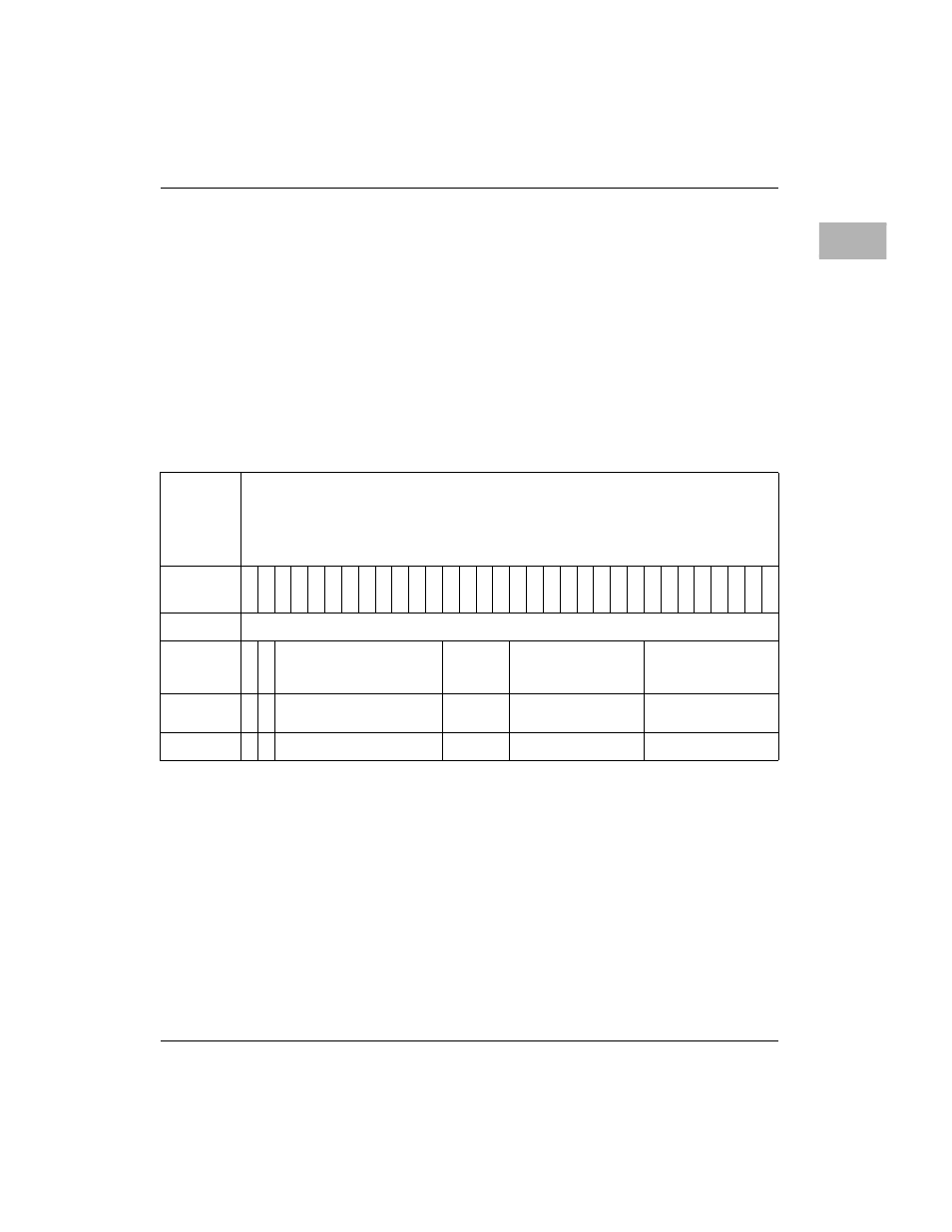
Timer Vector/Priority Registers
MASK
Mask. Setting this bit disables any further interrupts from
this source. If the mask bit is cleared while the bit
associated with this interrupt is set in the IPR, the interrupt
request will be generated.
ACT
Activity. The activity bit indicates that an interrupt has
been requested or that it is in-service. The ACT bit is set
to a 1 when its associated bit in the Interrupt Pending
register or In-Service register is set.
Offset
Timer 0 - $01120
Timer 1 - $01160
Timer 2 - $011A0
Timer 3 - $011E0
Bit
3
1
3
0
2
9
2
8
2
7
2
6
2
5
2
4
2
3
2
2
2
1
2
0
1
9
1
8
1
7
1
6
1
5
1
4
1
3
1
2
1
1
1
0 9 8 7 6 5 4 3 2 1 0
Name
TIMER VECTOR/PRIORITY
MA
S
K
ACT
PRIOR
VECTOR
Operation
R/W
R
R
R/W
R
R/W
Reset
1
0
$000
$0
$00
$00