Melsec-q, 3 specifications – MITSUBISHI ELECTRIC QJ71C24N User Manual
Page 80
3 - 30 3 - 30
MELSEC-Q
3 SPECIFICATIONS
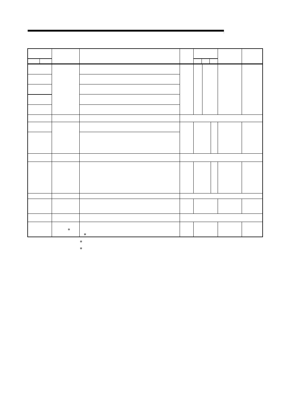
Address
Decimal (Hex)
Applicable
protocol
CH1
CH2
Application
Name
Initial
value
MC Non
Bi
Registration
allowed/not
allowed
Reference
section
8944 (22F0
H
)
Callback permit accumulated count
0 or more : Accumulated count
8945 (22F1
H
)
Callback denial accumulated count
0 or more : Accumulated count
8946 (22F2
H
)
Auto (callback) connection permit accumulated count
0 or more : Accumulated count
8947 (22F3
H
)
Auto (callback) connection denial accumulated count
0 or more : Accumulated count
8948 (22F4
H
)
For callback
function
Accumulated count of callback receive procedure cancel
0 or more : Accumulated count
0
RW
—
Not allowed
Section
8.6.2
Chapter 3 of
User's
Manual
(Application)
8949 to 8954
(22F5
H
to 22FA
H
)
Use prohibited
System area
—
8955 (22FB
H
)
Accumulated count of unlock process normal completion
0 or more: Accumulated count of normal completion
8956(22FC
H
)
For the remote
password
function
Accumulated count of unlock process abnormal completion
processing
0 or more: Accumulated count of abnormal completion
0
RW
—
Not allowed
Section
5.1.5
Section
8.6.2
Chapter 3 of
User's
Manual
(Application)
8957 to 8958
(22FD
H
to
22FE
H
)
Use prohibited
System area
—
8959(22FF
H
)
For the remote
password
function
Accumulated count of lock process based on circuit disconnection
0 or more: Accumulated count of lock process based on circuit
disconnection
0
RW
—
Not allowed
Section
5.1.5
Section
8.6.2
Chapter 3 of
User's
Manual
(Application)
9216(2400
H
)
Use prohibited
System area
—
9217(2401
H
)
For flash ROM
write count
housing
Flash ROM write count
0 to 1000: Write count
0
R
Not allowed
—
9218 to 9427
(2402
H
to 25FF
H
)
Use prohibited
System area
—
9728 to 16383
(2600
H
to 3FFF
H
)
For user (
1)
User free area 2 (6656 words)
(Transmission/receiving data monitoring function default buffer)
Usage is determined by the user.
0
RW
Not allowed
—
1 Only QJ71C24N (-R2/R4) is usable. (System area when using QJ71C24 (-R2)
2 The following tables show the areas of block monitoring devices No. 1 to 10 (CH1
side: 8272 to 8361 (2050
H
to 20A9
H
), CH2 side: 8528 to 8617 (2150
H
to 21A9
H
)),
which are assigned for designating the PLC CPU monitoring function.