3 sequence program for transmission data, Melsec-q – MITSUBISHI ELECTRIC QJ71C24N User Manual
Page 145
6 - 25 6 - 25
MELSEC-Q
6 DATA COMMUNICATION USING THE NON PROCEDURE PROTOCOL
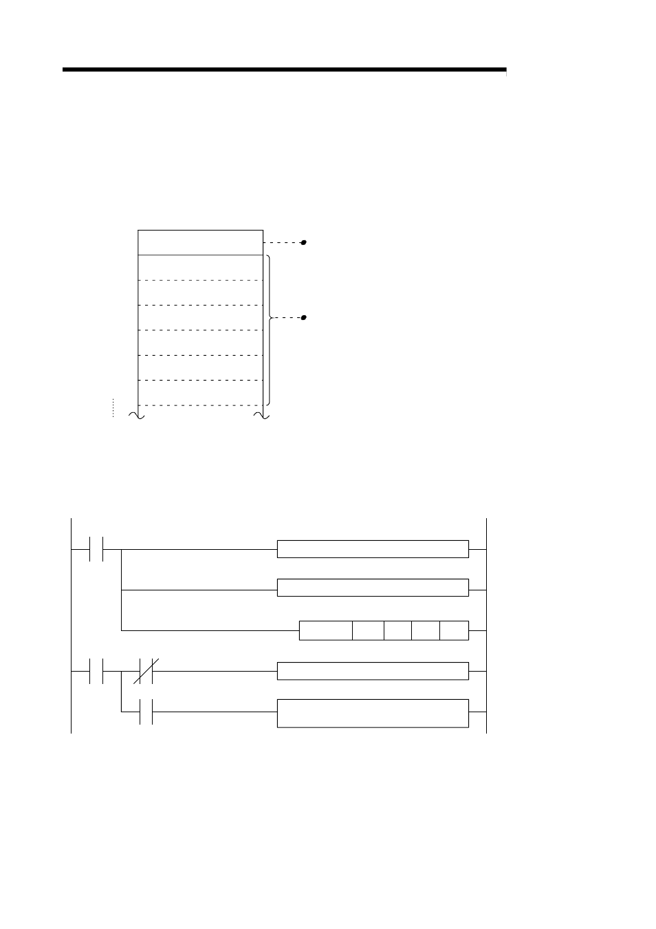
(2) Transmission data arrangement
The following example shows an arrangement of the transmission data to be sent
to the external device when storing it in the transmission area.
(Example) When transmitting "ABCDEFG123" (The transmit area is the default
value.)
CH1 side
address
400
H
401
H
402
H
403
H
404
H
405
H
406
H
5 or 10
(B)
42
H
(A)
41
H
(C)
43
H
(D)
44
H
(E)
45
H
(F)
46
H
(G)
47
H
(1)
31
H
(2)
32
H
(3)
33
H
(5)
35
H
(4)
34
H
1)
2)
Buffer memory
Transmission data count storage area
In accordance with the word/byte units designation
Word units....5
Bytes units....10
Transmission data designation area
Sequentially store the transmission data to low address (L)
→
(H), next
address (L)
→
(H), in the order of transmission.
6.2.3 Sequence program for transmission data
A sequence program for transmission data is explained below.
For details on the OUTPUT instruction used for data transmission, see Chapter 9.
G.OUTPUT
Un
D0
D11
M0
M0
M1
M1
(In case of the CH1 side)
Transmission
instruction
Create transmission data from D11
Create control data from D0
Processing for normal completion
Processing for abnormal completion
(retransmission, etc.)