Melsec-q, 3 specifications – MITSUBISHI ELECTRIC QJ71C24N User Manual
Page 78
3 - 28 3 - 28
MELSEC-Q
3 SPECIFICATIONS
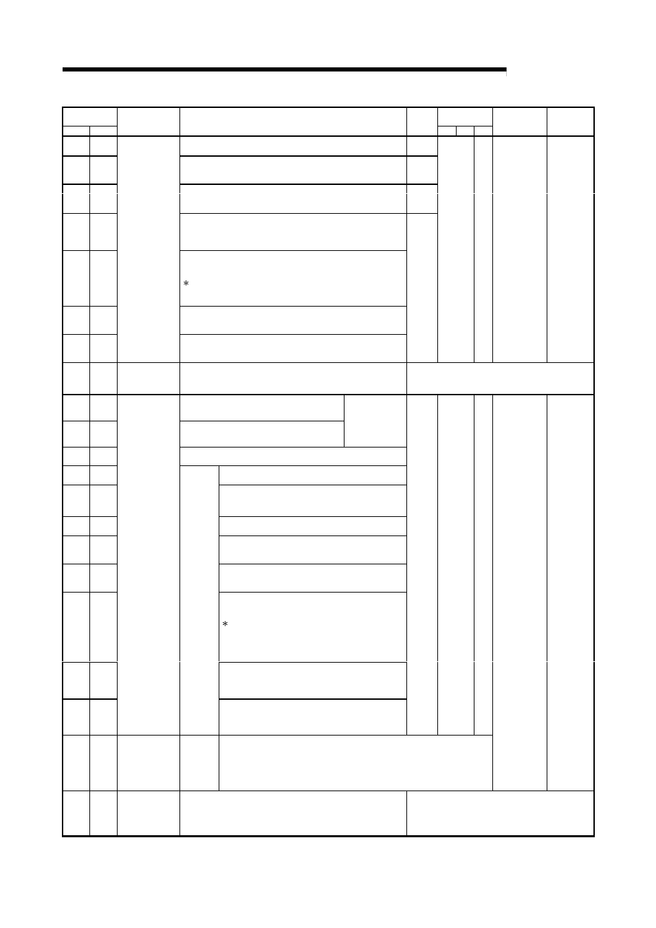
Address
Decimal (Hex)
Applicable
protocol
CH1
CH2
Application
Name
Initial
value
MC Non
Bi
Registration
allowed/not
allowed
Reference
section
Cycle time units designation
8256
(2040
H
)
8512
(2140
H
)
0: 100 ms
1: s
2: min
2
Cycle time designation
8257
(2041
H
)
8513
(2141
H
)
0
H
: No designation
1
H
to FFFF
H
: PLC CPU monitoring cycle time
5
H
PLC CPU monitoring function designation
0: Do not use the function.
1: Fixed cycle transmission
8258
(2042
H
)
8514
(2142
H
)
2: Condition agreement transmission
0
PLC CPU monitoring transmission measure designation
(for fixed cycle transmission)
8259
(2043
H
)
8515
(2143
H
)
0: Data transmission (device data and CPU status data)
1: Notification
8260
(2044
H
)
8516
(2144
H
)
Transmission pointer designation (For fixed cycle transmission and
data transmission)
1 to 100: Output head point (send from the nth)
Send the user frames designated in the following transmission
frame No. designation areas from the designated pointer position.
(addresses: CH1 side = BA
H
to 11D
H
, CH2 side = 15A
H
to 1BD
H
)
Output count designation (for fixed cycle transmission and data
transmission)
8261
(2045
H
)
8517
(2145
H
)
1 to 100:Output count (designate the number of frame transmissions.)
Data No. for connection designation (for fixed cycle transmission
and notification)
8262
(2046
H
)
8518
(2146
H
)
For designation
of PLC CPU
monitoring
function
0BB8
H
to 0BD5
H
, 8001
H
to 801F
H
: Data No. for connection
0
R
—
Allowed
Chapter 2
of User's
Manual
(Application)
8263 to
8268
(2047
H
to
204C
H
)
8519 to
8524
(2147
H
to
2149
H
)
Use prohibited
System area
—
Number of registered word blocks designation
8269
(204D
H
)
8225
(214D
H
)
0 : No designation
1 to 10: Number of blocks of word devices
Number of registered bit blocks designation
8270
(204E
H
)
8226
(214E
H
)
0 : No designation
1 to 10: Number of blocks of bit devices
It is possible to
designate a
maximum of 10
blocks in total.
PLC CPU abnormal monitoring designation
8271
(204F
H
)
8527
(214F
H
)
0: Do not monitor.
1: Monitor.
Monitoring device designation
8272
(2050
H
)
8528
(2150
H
)
90
H
to CC
H
: Device code
Head device No. designation
8273 to
8274
(2051
H
to
2052
H
)
8529 to
8530
(2151
H
to
2152
H
)
0 or more: Head device No.
Read point designation
8275
(2053
H
)
8531
(2153
H
)
1 or more: Number to read points
Monitoring condition designation (judgment condition
designation)
8276
(2054
H
)
8532
(2154
H
)
1 or more: Monitoring condition
Monitoring condition value designation
8277
(2055
H
)
8533
(2155
H
)
At bit device 0: OFF 1: ON
At word device 0 to FFFF
H
: Monitoring condition value
8278
(2056
H
)
8534
(2156
H
)
Transmission pointer designation (for condition
agreement transmission and data transmission)
1 to 100: Output head point (send from nth)
Send the user frames designated in the following
transmission frame No. designation areas from the
designated pointer position.
(address: CH1 side = BAH to 11DH, CH2 side = 15AH
to 1BDH)
Output count designation (for condition agreement
transmission and data transmission)
8279
(2057
H
)
8535
(2157
H
)
1 to 100: Output count (designate the number
of frame transmissions)
Data No. for connection designation (for condition
agreement transmission and notification)
8280
(2058
H
)
8536
(2158
H
)
For designation
of PLC CPU
monitoring
function
No. 1
block
monitoring
device
0BB8
H
to 0BD5
H
, 8001
H
to 801F
H
: Data No. for
connection
0
R
—
8281 to
8361
(2059
H
to
20A9
H
)
8537 to
8617
(2159
H
to
21A9
H
)
For designation
of PLC CPU
monitoring
function
Block
monitoring
devices
No. 2 to
10
The structure of each area is the same as the first block monitoring device area
See *2 for the details of each area.
Allowed
Chapter 2
of User's
Manual
(Application)
8362 to
8421
(20AA
H
to
20E5
H
)
8618 to
8677
(21AA
H
to
21E5
H
)
Use prohibited
System area
—