5 state transition diagram, State transition diagram – FUJITSU Semiconductor Controller MB89950/950A User Manual
Page 77
63
CHAPTER 3 CPU
3.7.5
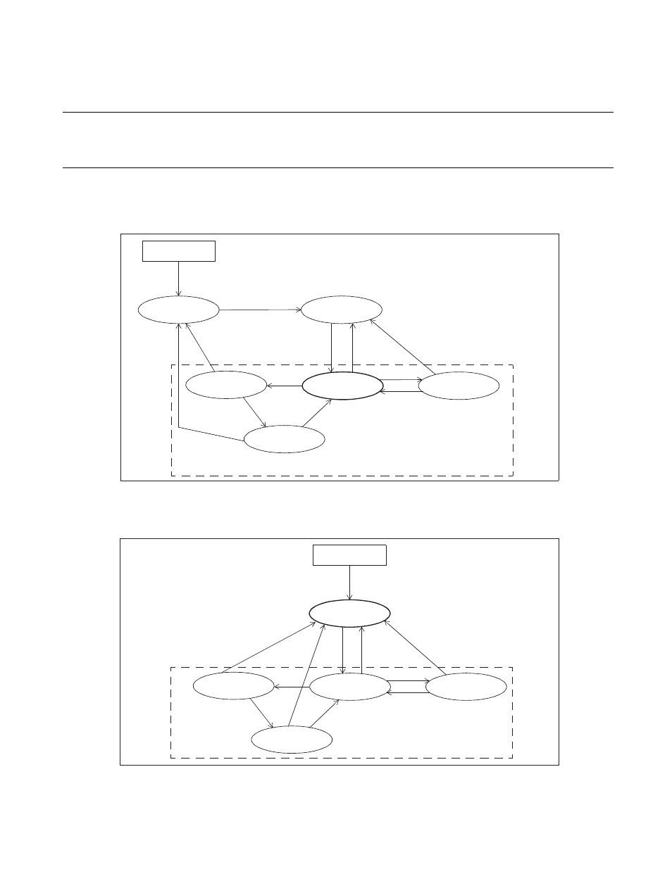
State Transition Diagram
This section shows two state transition diagrams: one diagram for "with power-on
reset" option products and the other for "without power-on reset" products.
■ State transition diagrams
Figure 3.7-2 State transition diagram (products with power-on reset)
Figure 3.7-3 State transition diagram (products without power-on reset)
Power-on
Oscillation stabilization
delay reset state
Reset state
Power-on reset
Stop mode
RUN state
Sleep mode
Clock mode
Main clock oscillation
stabilization delay
[1]
[2]
[3]
[3]
[2]
[1]
[8]
[5]
[6]
[7]
[4]
Power-on
Reset state
Stop mode
RUN state
Sleep mode
Clock mode
Main clock oscillation
stabilization delay
[1]
External reset
[2]
[3]
[3]
[2]
[1]
[5]
[6]
[7]
[4]
[8]