2 block diagram of 8-bit pwm timer, Block diagram of 8-bit pwm timer – FUJITSU Semiconductor Controller MB89950/950A User Manual
Page 138
124
CHAPTER 7 8-BIT PWM TIMER
7.2
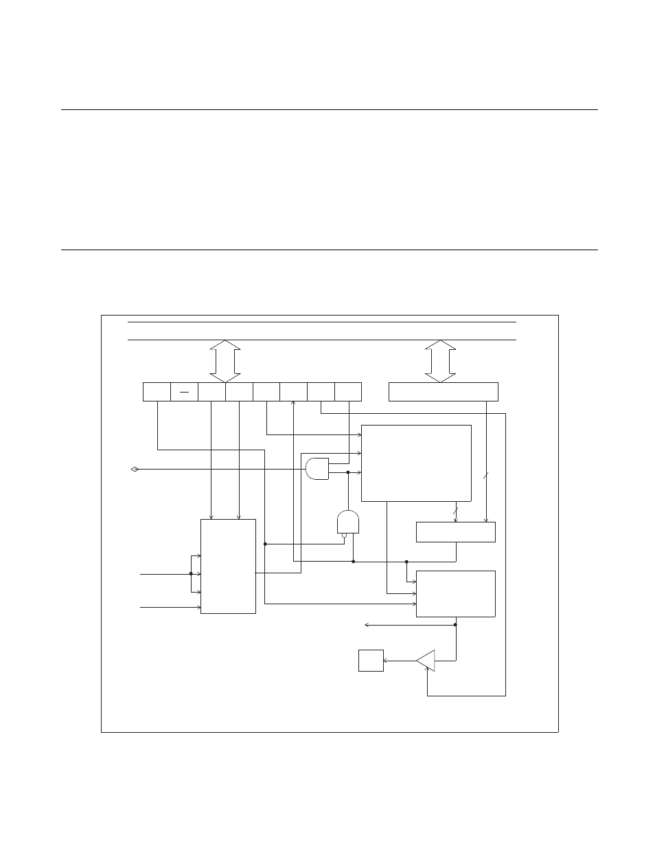
Block Diagram of 8-bit PWM Timer
The 8-bit PWM timer consists of the following six blocks:
• Count clock selector
• 8-bit counter
• Comparator circuit
• PWM generator and output controller
• PWM compare register (COMR)
• PWM control register (CNTR)
■ Block diagram of 8-bit PWM timer
Figure 7.2-1 Block diagram of 8-bit PWM timer
P/T
P1
P0
TPE
TIR
OE
TIE
Internal data bus
COMR
PWM compare register
IRQ2
Start
CLK
Clear
Over flow
8-bit
counter
Comparator circuit
Count clock
selector
X 1
X 16
X 64
PWM generator
and
output controller
Out
put
Pin
Out
pu
t pi
n cont
rol
b
it
PWC timer output
1 t
inst
Timer/PWM
CNTR
8
8
P41/PWM
To UART
t
inst
: Instruction cycle (4/F
CH
)