6 operation of pwm timer function, Operation of pwm timer function – FUJITSU Semiconductor Controller MB89950/950A User Manual
Page 148
134
CHAPTER 7 8-BIT PWM TIMER
7.6
Operation of PWM Timer Function
This section describes the operation of the PWM timer function of the 8-bit PWM timer.
■ Operation of PWM timer function
Figure 7.6-1 "PWM timer function settings" shows the settings required to operate as the PWM timer
function.
Figure 7.6-1 PWM timer function settings
On activation, the counter starts to count up from "00
H
" on the rising edge of the selected count clock. The
PWM pin (PWM) outputs (PWM waveform) an "H" level until the counter value matches the value set in
the COMR register. From the match until the counter value overflows (FF
H
--> 00
H
), the PWM pin outputs
an "L" level.
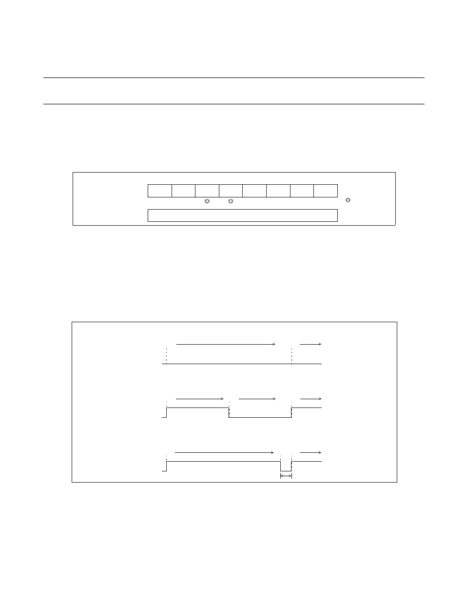
Figure 7.6-2 "Example of PWM waveform output (PWM pin)" shows the PWM waveforms output from
the PWM pin.
Figure 7.6-2 Example of PWM waveform output (PWM pin)
Note:
Do not change the count clock cycle (CNTR: P1, P0) during operation of the PWM timer function
(CNTR: TPE = "1").
Reference:
When the PWM timer function is selected, the PWM pin maintains its existing level when the counter is
stopped (CNTR: TPE = "0").
Bit 7
Bit 6
Bit 5
Bit 4
Bit 3
Bit 2
Bit 1
Bit 0
CNTR
P/TX
—
P1
P0
TPE
TIR
OE
TIE
1
1
X
1
X
X
COMR
Sets "H" width of pulse (compare value).
: Used bit
: Unused bit
1 : Set "1".
For COMR register value of "00
H
" (duty ratio = 0%)
Counter value
00
H
H
L
H
L
H
L
00
H
00
H
Counter value
Counter value
PWM waveform
PWM waveform
PWM waveform
For COMR register value of "80
H
" (duty ratio = 50%)
For COMR register value of "FF
H
" (duty ratio = 99.6%)
FF
H
00
H
FF
H
00
H
FF
H
00
H
80
H
One count clock cycle width