5 operation of serial output, Operation of serial output – FUJITSU Semiconductor Controller MB89950/950A User Manual
Page 195
181
CHAPTER 9 8-BIT SERIAL I/O
9.5
Operation of Serial Output
The 8-bit serial I/O can perform serial output of 8-bit data synchronized with a shift
clock.
■ Serial output operation
Serial output can operate using an internal or external shift clock. When serial output operation is enabled,
the contents of the SDR register are output to the serial data output pin (SO). Serial input is performed at
the same time.
●
Internal shift clock
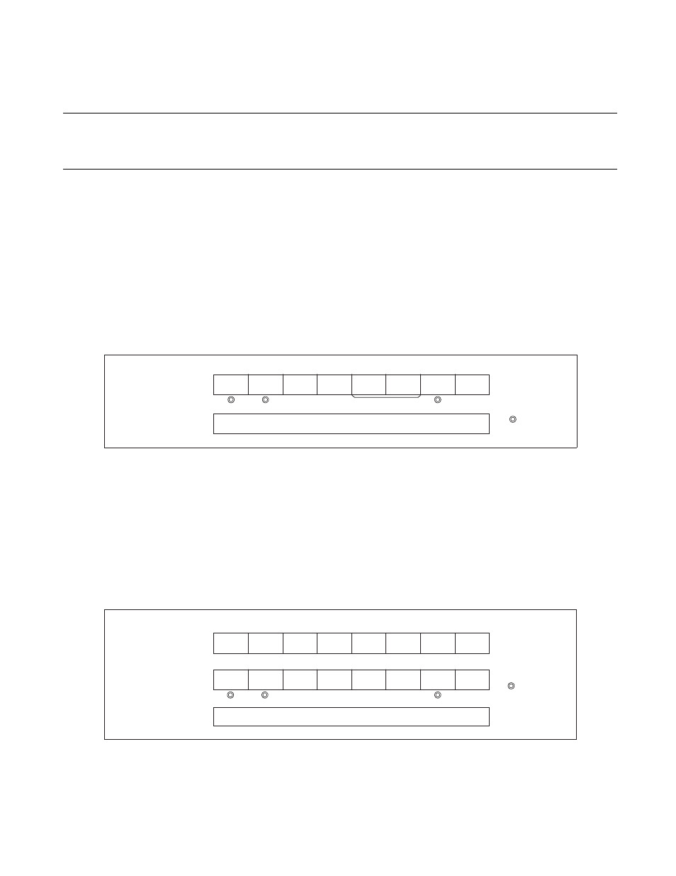
Figure 9.5-1 "Serial output settings (when using internal shift clock)" shows the settings required to operate
serial output using an internal shift clock.
Figure 9.5-1 Serial output settings (when using internal shift clock)
Activating serial output operation outputs the contents of the SDR register to the SO pin, synchronized with
the falling edge of the selected internal shift clock. At this time, the device being communicated with (a
serial input) must be waiting for input of the external shift clock.
●
External shift clock
Figure 9.5-2 "Serial output settings (when using external shift clock)" shows the settings required to operate
serial output using an external shift clock.
Figure 9.5-2 Serial output settings (when using external shift clock)
Enabling serial output operation outputs the contents of the SDR register to the SO pin, synchronized with
the falling edge of the external shift clock. When serial output completes, reset the SDR register and enable
operation (SMR: SST = "1") promptly for output of the next data.
SMR
SIOF
SIOE
SCKE
SOE
CKS1
CKS0
BDS
SST
1
1
other than "11"
1
SDR
Sets transmit data.
: Used bit
1: S
et "1"
Bit 7
Bit 6
Bit 5
Bit 4
Bit 3
Bit 2
Bit 1
Bit 0
DDR
0
X
X
X
X
X
X
X
X
SMR
SIOF
SIOE
SCKE
SOE
CKS1
CKS0
BDS
SST
SDR
Sets transmit data.
: Used bit
: Unused bit
1 : Set "1"
0 : Set "0"
Bit 7
Bit 6
Bit 5
Bit 4
Bit 3
Bit 2
Bit 1
Bit 0
0
1
1
1
1