6 operation of pulse width measurement function, Operation of pulse width measurement function – FUJITSU Semiconductor Controller MB89950/950A User Manual
Page 173
159
CHAPTER 8 PULSE WIDTH COUNT TIMER (PWC)
8.6
Operation of Pulse Width Measurement Function
This section describes the operations of the pulse width measurement function of the
pulse width count timer.
■ Operation of pulse width measurement function
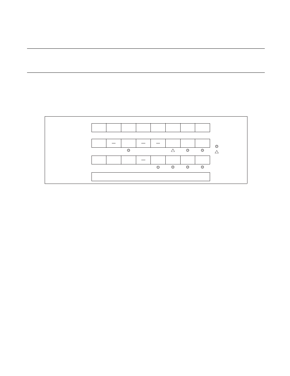
Figure 8.6-1 "Pulse width measurement function settings" shows the settings required to operate as the
pulse width measurement function.
Figure 8.6-1 Pulse width measurement function settings
When counter operation is enabled, the counter starts to count down from "FF
H
" when a measurement start
edge is detected on the pulse input to the PWC pin. (For "H" level measurement, the counter starts
measurement from the next rising edge if the input is already "H".)
On detection of the measurement completion edge, the current down counter value is transferred to the
PWC reload buffer register (RLBR), the measurement completion interrupt request flag bit (PCR1: IR) and
buffer full flag bit (PCR1: BF) are both set to "1", and counter operation is re-enabled. (The function
supports continuous pulse width measurement and so can be used like an input capture.)
Figure 8.6-2 "Example of "H" width measurement using pulse width measurement function" shows the
operation when the measured pulse selection bits (PCR2: W1, W0) are set to "00
B
" ("H" width
measurement).
Bit 7
Bit 6
Bit 5
Bit 4
Bit 3
Bit 2
Bit 1
Bit 0
DDR4
0
PCR1
EN
IE
UF
IR
BF
1
PCR2
FC
RM
TO
C1
C0
W1
W0
1
RLBR
Holds the pulse width measurement value.
: Used bit
: Used to
measure long
pulse widths
: Unused bit
1 : Set "1".
0 : Set "0".
X
X
X
X
X
X
X
X
X
X