Connecting the external device, Setting up an external device, Executing the load operation – Fostex D2424 User Manual
Page 89: You will use the “load pgm ?” menu in setup mode, Output input output, Input
Model D2424 Reference Manual (Saving and Loading Song Data)
89
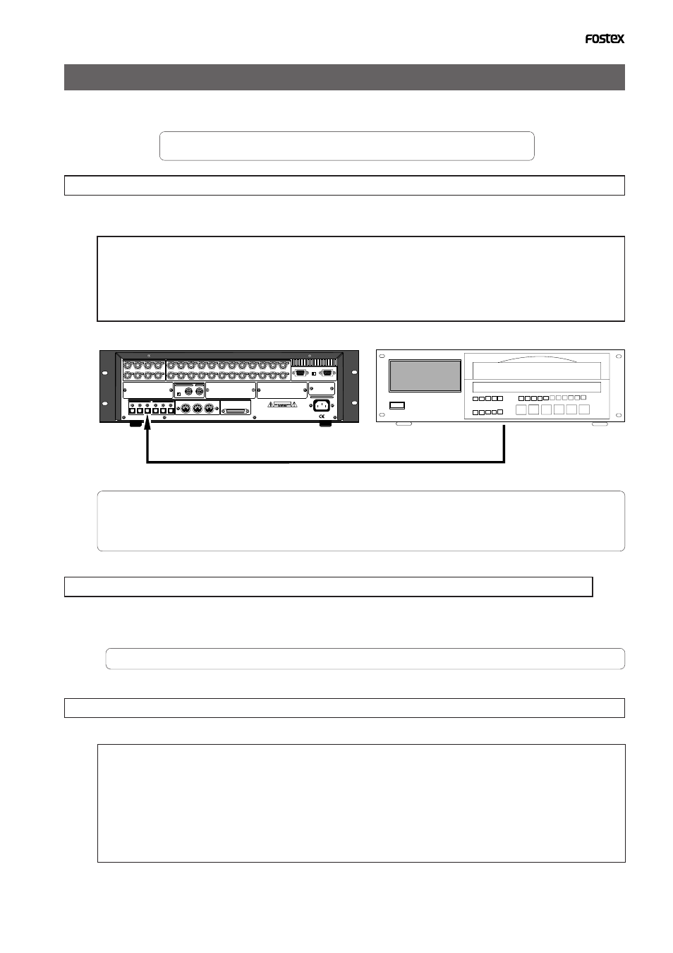
Loading the data using a adat or S/P DIF digital signal
Load the data by S/P DIF digital signals (or adat digital signals) from the [DATA INPUT] jack of the
recorder.
* Restore the initial settings on the recorder.
* Set the same sampling rate on the external digital device and the recorder.
Connecting the external device
Connect [DATA INPUT] connectors of the recorder to the digital output connectors on the external
digital device.
• The recorder has [DATA INPUT] connectors for an S/P DIF digital signal (OPTICAL) and for an adat digital
signal. These connectors have the same shape but carry different information.
Use the [DATA INPUT 1-8] connector. Do not use the [DATA INPUT 9-16] and [17-24] connectors.
• Do not remove the optical cable or perform any other operation that would disconnect the S/P DIF signal until
the session is complete. Otherwise, the recorder will generate noise, and affect the connected device.
• If the external device has only COAXIAL type (RCA) digital I/O connectors, connect an optional COP-1/96k
(optical/coaxial converter) to use an S/P DIF digital signal.
• Connecting both output and input connectors on the recorder to the input and output connectors on the
external digital device respectively may generate a digital loop.
Setting up an external device
1.Setup the external device so that it can output a digital signal.
2.Locate the beginning of the pilot signal recorded in the saved data.
* Refer to the instruction manual that came with your external digital device for details.
Executing the load operation
You will use the
“Load PGM ?”
menu in Setup mode.
75
Ω
WORD
OUTPUT
INPUT
OUTPUT
DATA
16 - 9
24 - 17
8 - 1
100
Ω
RS422
THRU
AC-IN
INPUT
16 - 9
24 - 17
8 - 1
SCSI
ON OFF
REMOTE
MIDI
INPUT
THRU
OUTPUT
1
2
3
4
5
6
7
8
1
2
3
4
13
14
15
16
5
6
7
8
17
18
19
20
9
10
11
12
21
22
23
24
NE PAS OUVRIR
CAUTION
AVIS: RISQUE DE CHOC ELECTRIQUE
WARNING:
TO REDUCE THE RISK OF FIRE OR ELECTRIC
SHOCK, DO NOT EXPOSE THIS EQUIPMENT
TO RAIN OR MOISTURE.
ANALOG INPUT BALANCE [ +4dBu ] / UNBALANCE [ -10dBv ]
ANALOG OUTPUT BALANCE [ +4dBu ] / UNBALANCE [ -10dBv ]
ON OFF
DATA
MIDI
WORD
SCSI
REMOTE
ANALOG OUTPUT BALANCE [ +4dBu ] / UNBALANCE [ -10dBV ]
ANALOG INPUT BALANCE [ +4dBu ] / UNBALANCE [ -10dBV ]
• Input format available
: adat, SPDIF, SCSI, IDE2
• Programs available
: When using an adat/SPDIF ->P01 - P99 (each program individually)
: When using a SCSI/IDE2
->P01 - P99 or All program
• Track available
: When using an adat or DAT ->Tracks 1-8, 1-16, 1-24, 1-32, 1-40
1-48, 1-56, 9-16, 9-24, 9-32, 9-40, 9-48, 9-56, 17-24, 17-32, 17-40
17-48, 17-56, 25-32, 25-40, 25-48, 25-56, 33-40, 33-48, 33-56,
41-48, or 49-56
: When using a SCSI/IDE2
->All tracks (1-56) will be automatically
selected.
DATA INPUT 1-8
adat or DAT
adat Out (or Digital Out)